
BobMic
Members
-
Joined
-
Last visited
Everything posted by BobMic
-
Starting to make more sense to me now, thanks! I wasn't thinking about thread as being a radio path separate from WiFi. I haven"t used any Zigbee devices so the light (in my head) just didn't go on. I just did some reading on Zigbee transport protocol and network stack. For sure the devices that I'm using (TP15) is a WiFi 802.11 device with Bluetooth commissioning. No need for thread which is what I guessed but didn't completely understand why...until now.
-
When you say "gets routed over the router" are you talking about my network router or the border router? I looked at my router and all three devices are on the IPv4 list, none on the v6 list. I don't have any devices that require thread.
-
I have been working with Javier on this. He informed me that after making the connection via Alexa (and probably others), generating a setup code and connecting to eisy, the device can be deleted from Alexa. UDM and eisy will still have full control and rights to the device. Of course if the device requires a "thread" connection you will still need it configured in your Alexa or other Thread Border Router as eisy does not have that capability yet. The TP15 does not require a thread connection so works fine.
-
Thanks for pointing that out and directing me to some good information. I'm new to Alexa, had a dot sitting around for a couple of years still in the box. A web search led me to the fact that several echo devices will work as a threads border router. I tried the dot g2 which of course didn't work but got me interested in Alexa. I bought an "Echo g4" which I wrongly assumed was the current "Dot". I have edited my original post to correct that.
-
Thanks Guy. I got that tip from a thread that I found but there was no detail so wanted to make the step-by-step to save new comers the 3-4 hours that it took me to get the sequence and details correct. I'm new to Matter and also Alexa. I have been using isy and Insteon for many years but it was a bit fiddly.
-
I have been unable to add the TP15 directly to Eisy using Matter. When I try I get UD mobile to scan the QR code but it never completes the configuration. This it with the current beta Matter, UDMobile 1.5.2. I have also tried using the Matter code with the same results. The work-around that I have found is to use an Echo (gen 4 to serve as a “thread border router”. There are several Alexa devices that will do this. Here is a detailed procedure, sorry to the experts for the step-by-step but I want to make it clear for anyone. First do NOT configure the TP15 through the Tapo app. It will connect fine to the Echo but you can’t get a forwarding code from Alexa. If you have it installed in Tapo, just delete it and do a reset. Plug the TP15 into an outlet. Open the Alexa app – go to Devices, +, Add Device, other, Matter and follow the instructions (note, don’t use the default Alexa install for the TP15. I expect it installs with another protocol instead of Matter). Once the device is found you can name it for use with your echo (name doesn’t carry over to UD). Now in the Alexa app select the TP15 device, settings (gear icon), Other Assistants and Apps, add another (+), copy the set-up code to the clipboard or write it down. Open UD Mobile, settings (gear icon bottom right), Matter, add (+), paste or enter the code (hyphens not required), submit. It took a while so be patient. Accept the synchronize pop-up. The new device will appear as ZM XXX.1 On-Off Switch. Tap on it to change the name and save (it won’t show the new name yet). Open Admin Console – Matter tab, synchronize, new & deleted, yes. It will appear with the new name. You can now move it into a folder, add it to scenes & programs as it is now a fully integrated node. Go back to UD Mobile and synchronize. The name will update. This may work with other TP-Link devices but the TP15 is the only one that I have to test with. I hope this helps someone get through this much easier than it was for me. I’m sure UD will fix the direct connect before Matter goes to full release.
-
Several years (Pre UDM) I did a l-o-n-g write up on KPL controlling a fanlink using Mobilinc. I don't recommend reading it unless you are very new to setting up KPL/fanlink but am including it in case someone needs step by step. Just disregard all of the Mobilinc stuff and control the "scenes" in UDM as recommended by Javi above.
-
Is there a way to reorder entries in the main UDM like there is in Favorites? They seem to be alphabetically listed. Works great to long press and move in favorites!
-
Thank you, works perfectly! I guess the learning curve is much more shallow when you ask the architect. My setup is much simpler with just scenes and I only control it with the KPL's and UDM so never gets out of sync. Thanks for the quick response, Bob
-
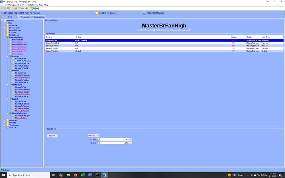
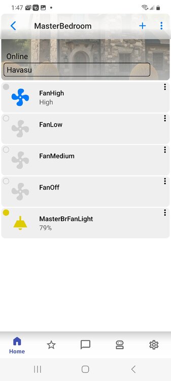
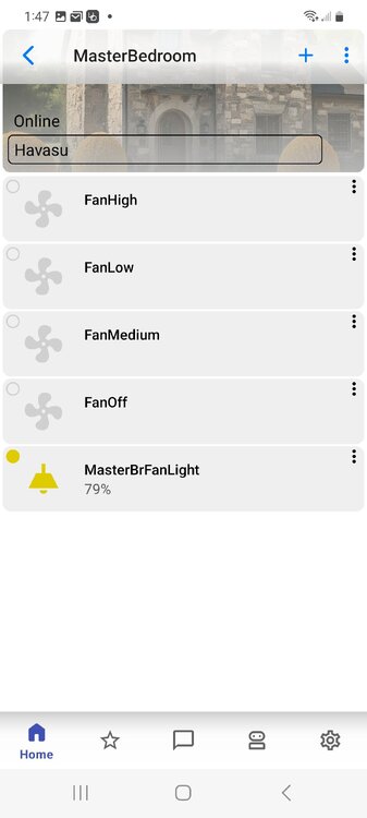
Here are a couple of screenshots.
-
I have been using UD Mobile for a couple of years in it's pretty much raw form. Over the lest few days I have gone wild customizing both of my house's favorites entry's. I am amazed at what I have missed and first would I would like to thank you for a very versatile application! I am having a little trouble with the steep learning curve when it comes to the "Command Type" and it seems like that may be the solution to the title of this post. Hopefully it's easier than that and I just didn't find it yet. I have several KPL devices at my lake house controlling fans. I am using scenes for each of the buttons to make the buttons exclusive and control the fanlink. Everything works great with the KPL's and the buttons in UDM with the exception of a double press turns that button off. I am trying to emulate the KPL which is set to Non-toggle (on) so each press is a momentary push button calling the associated scene and multiple presses of the same button don't affect the state. How can I accomplish the same functionality in UDM? The easy answer would be to add a "Type" for a momentary button with the choice of on or off on each press rather than toggle. Thanks, Bob
-
Update on this. I was again fighting the status of the button LED's not matching what the management console was showing when the scenes were triggered in Mobilinc. It turns out that the older 2486 KPL's don't work correctly. When I select a fan speed in Mobilinc all four button LED's light. The correct speed is set and the management console shows the correct LED lit and the other three off but that is not the case on the KPL, all four are lit. It works perfectly on the 2334 KPL's.
-
Interesting, that's not the case for irrigation controller. All of the header pins for the daughter board, except for v+ (1) and GND (8), go to IO pins in the PIC microcontroller. The program in the PIC 16F648A must be the same for USB and Serial, it's not on the irrigation base boards. For one thing pin 6 on the header has a 1OOhz 1ms clock pulse. Header pinout 1 - +21v 2 - PIC pin 9 RB2/TX/CK 3 - PIC pin 12 RB5 4 - PIC pin 14 RB7 5 - PIC pin 8 RB1/RX/DT 6 - PIC pin 11 RB4 7 - PIC pin 13 RB6 8 - GND
-
I tried to use a 2413U base board to replace the base board in a EzFlora and it didn't work. There is a PIC Microcontroller on the base board and for sure it has a different program loaded on the EzFlora. It seems like the daughter boards are just IO interfaces and the programming is in the PIC on the main board.
-
I just tested my config and double tap of any button does put the fan controller in high and the buttons are out of sync. I think you are right in that the only way to get around that is to use a program that sets the fan and LEDs status for an "on" or "fast-on" to the same appropriate level. That may be what led me to hide all but the "on" button in Mobilinc. Thanks for pointing that out!
-
Not sure because I don't use the admin console to control them. Most of my problems were related to Mobilinc Pro and that was my motivation to do the testing and write up. I'll test the double tap and report back. Notice I removed all buttons in Mobilinc except for the "on" button which I renamed to "select" because I was getting unreliable results with other buttons so my "select" gave the same results every time.
-
Thanks, it took quite a while but now I have a standard procedure. Buttons worked fine but I have never been satisfied with the way Mobilinc was controlling it. That's why I decided to push every button and check/uncheck every box to find the closest path to my Mobilinc goal. That's a great addition to my bag of tricks, thanks! I have never tried toggling a fan speed on and off so didn't realize the off is redundant. I like the idea that the fan and light can be controlled by the four buttons and the local up/down dimmer can be used for something else. Another option is an eight button KPL controlling two fan/light systems. Now you need to spend half a day sorting out how to write that up so anyone can understand...?
-
After reading many posts on keeping status in sync on this setup and having mixed results for a very long time, I have created a step by step of my best results. I welcome all comments and corrections. I am by no means an expert but have tried to explain why I have done things the way I did and what the outstanding issues are. To put all of that in a format that I hope anyone can understand and learn the Intricacies of Mobilinc - KPL LEDs and scenes, ended up quite long. I'm sure the experts will be bored to death but I expect some will get what they need. I also hope the experts will improve on the things that I still struggle with. Fanlinc – KPL keypad – Mobilinc Pro Link Fanlinc controller and Keypad. Check box “remove existing links” box. Create separate folders for the devices and the scenes. Name them to whatever makes sense to you. Move Fanlinc and the five keypad devices into the devices folder. Rename Keypad buttons and Fanlinc devices. – note order in Mobilinc is alpha/numeric so put 1,2,3&4 ahead of 1-High, 2-Med, 3-Low & 4-Off. If you don’t do this the order will be High, Low, Med & Off, alphabetically in Mobilinc. This is the only way I have found to order things in Mobilinc Pro. Set button toggle mode to "all non-toggle on" then set light button to toggle. Create a scene for each button, Light, 1-High, 2-Med, 3-Low & 4-Off. Again, to keep the order correct in Mobilinc, put 1,2,3,4 in front of the scene names. Move the scenes into the scenes folder and build the scenes with the devices and the buttons as follows. Add the Light device to the Light scene and the Fan device to each of the fan scenes as responders. Add the Light button to the Light scene as a controller. Add the Fan 1-High button to the 1-High scene as a controller, add the 2-Med, 3-Low & 4-Off buttons as responders. Add the Fan 2-Med button to the 2-Med scene as a controller, add the 1-High, 3-Low & 4-Off buttons as responders. Add the Fan 3-Low button to the 3-Low scene as a controller, add the 1-High, 2-Med, & 4-Off buttons as responders. Add the Fan 4-Off button to the 4-Off scene as a controller, add the 1-High, 2-Med & 3-Low buttons as responders. The next steps set up the “scenes” items to the desired states when selected in Mobilinc. Click on the 1-High scene, select 2-Med at the top of the page, change it to “off” and click the “update” button on the bottom of the page. Set 3-Low & 4-Off to off the same way. Leave the Fan controller set to high and the 1-High (controller button) set to “default”. The on and off state of the buttons reflects the LED state when the “Scene” is selected in Mobilinc Pro. It does not set the status if the scene is selected with the KPL, we will do that later. Click on the 2-Med scene, select the Fan controller, set to med and click the “update” button at the bottom. Click on the 1-High, 3-Low and 4-Off, switch each to off and update, again leave the controller button set to default. Do the same for the 3-Low and 4-Off scenes respectively. The next steps set up the “scenes” items to the desired states when selected with the buttons on the KPL directly. The settings will be the same as for the scenes settings in the last group but instead of selecting the scene, click on the controller button in each scene and set the states. Click on the 1-High button (the controller) in the scene tree, select 2-Med at the top of the page, change it to “off” and click the “update” button on the bottom of the page. Set 3-Low & 4-Off to off the same way. Leave the Fan controller set to high and the 1-High (controller button) set to “default”. Click on the 2-Med controller button in the scene, select the Fan controller, set to med and click the “update” button at the bottom. Click on the 1-High, 3-Low and 4-Off, switch each to off and update, again leave the controller button set to default. Do the same for the 3-Low and 4-Off scenes respectively. Test buttons on the KPL while watching the fan controller, if they don’t stay in sync check the scene settings for each controller button in each scene. The controller button settings control the scene for button presses. The scene settings only affect the scene triggered by Mobilinc Pro. This took a while to sink in for me so I have repeated it and if it doesn't make sense read it again. This is very important to understand troubleshoots the LEDs when they are not staying in sync. This concludes the set up in the ISY. Mobilinc Pro Setup Make sure “Show Hidden Items” check box is not checked in Mobilinc Configuration. Hide all entries in the “My Devices” folder created above to prevent changes from being made to the fan/light controller or the KPL buttons directly which will get things out of sync with the KPL LEDs. Go into the “My Scenes” and the scene folder made above and select one of the fan button scenes. Choose “Advanced Options” at the bottom. At the top under “Custom Command Names” select and delete the text for each “BRIGHTEN, OFF, DIM, FAST ON and FAST OFF”. This will hide those buttons. Change the text for “ON” to “Select”. This select button is the only control you need to activate the scene. Using any of the other buttons just adds complications and there is no benefit. Change the icon to the fan icon. Select the Light button and advanced, change the icon to the chandelier icon. (my preference, you can use whatever you like) Don’t use the sliders in the Light scene or it will get out of sync. All the buttons will work correctly. Unfortunately, in the Android version of Mobilinc Pro the button icons don’t show the correct status and tapping on the icon does not work correctly. I believe this is caused by how Mobilinc presents a percentage based on all devices in the scene rather than the status of the controller in the scene. The correct status is displayed when you go into a button scene to select it. The icon tap seems to be an on/off toggle. Both the display and icon tap seems to work correctly in the iOS version. I hope this helps someone understand the interaction of these devices. Writing it up has made it very clear to me and I'm now in sync! Bob
-
It doesn't look like it does the handshake when I plug it in, LED just goes green solid. I have one of their units with the 2412. I thought it was an older version, it's labeled EZRain V1, has a blue LED and doesn't have a removable connector. It's the one I used to replace the problem one. It has a different daughter board also. Much smaller to leave room for the big transformer of the 2412.

-
Yes I made sure the pins engaged properly and even tested the voltage on the daughter card to male sure they were electrically engaged. I tried to auto link with the event viewer open on level 3 but the EZFlora doesn't go into "link mode" when I hold the set button. I tried one of my other EZFloras and it goes into link mode when the button is held but also didn't show up on the log or linking GUI. Thanks for the try, at least I know it is acting different than the good one by not entering linking mode. Pretty sure linking is a function of the 2413X and not the EZFlora daughter card. I may take the good one apart and test that by swapping the daughter cards.
-
I had one of my EZFlora Controllers stop responding so swapped it out with my spare and pulled out my kit of 2413-x capacitors and changed them out. When I try to link it to teat it fails with the "can not determine Insteon engine". I checked the power supplies and they seem fine at about 22v and 5v. I left my scope at work so can't check the ripple right now but am starting to think it may have not been a power supply poroblem. An added twist is that the address tag is missing so I restored an old backup to get the address but I am as sure I one can be that I have the correct address. I have done a reset in the EZFlora several times and it does what it's supposed to do , red LED and buzzer for about 10 seconds then LED goes green when I release. Is there anything else that I can check? Thanks, Bob
-
Thank you Larry!!! Exactly what I was looking for but just couldn't find the right key words to hit it I guess. My requirement is very similar to yours as I am trying to track my HVAC usage at the vacation house to trouble shoot a problem. The other thread is also very interesting and I will probably end up with a network module to do some long term tracking on a few things. Warmest regards, Bob
-
I would like to log the time of day and duration that my thermostat is calling for cooling during the day. I expect that there are many uses for logging device on times and duration but have not been able to find anything in the forums about how it could be done.
-
I've just added a 2982-222 Smoke Bridge and it seems to have linked correctly. I have seven entries in the ISY and am trying to figure out what the "current state" should be for each entry. The only one that has a state displayed is test which is always on after the first time I pressed test on the FirstAlert. I tried deleting it from the ISY and linking again but got the same response, no state displayed for any of the entries until I press test then test goes to "on" and stays on. I would expect test to go to off once the FirstAlert test cycle completes. I also expected the other entries to display something like off for Smoke and CO. Does anyone know what each of the entries does and should be displaying as a state and what their other possible states are? The entries are: Smoke CO Test Unknown Message Clear Low Bat Multifunction
-
Thanks Brian, I got the spec sheet. That makes sense that D7 is a Zener and R7 is its load. That would mean that if the voltage at the cathode of D6 exceeds the Zener voltage by ~ 1.2v the transistor in the opto drives a current into the feed-back of U1 to regulate the output. That would put the Zener at about 18.8v for the readings others have reported (20v). R6 may have some influence depending on its value but probably there to limit the current into the opto. Thanks for the tip on the through-hole. Probably what I need to do. I didn't get a chance to work on it last night and not sure when I will get another chance with Christmas almost here but I will report back once I get a look.


