
Brian H
Members
-
Joined
-
Last visited
-
I agree it maybe the power supply. Though your post seems to point more to the SD card. Maybe it got slightly corrupted at power loss or the accidental incorrect ZWave file messed something up. I have had a few over the years. One was weak and my ISY994i was fine until the power went out and then it refused to start. Just a loop of trying to boot, supply shut down and then it tried again.
-
Just some information. The Z Wave board was an option and not all versions ISY4i had Z Wave as sold but we could add one if we wanted too. Most electronics are now much more expensive. Even big vendors have chanced prices. Even Apple. Data centers are sucking up RAM and causing price changes upward.
-
Docs are also here but some maybe duplicates with different revisions. https://github.com/pyinsteon/pyinsteon/commit/2533494a8b13b30b2d0938c9a18afe782b740410
-
A new 2413U probably would be best. Even if stored for a backup. The 2413S serial PLM used by older ISY controllers has been discontinued by Insteon so older users may need to find a new way to replace the PLM or a rebuild.
-
Thank you for the information. We have seen other posts indicating caps didn't always correct things. 2.4 should have the updated serial port daughter board with the better serial interface chip and a surge protection network on the serial signals to the outside world. Along with the better caps. The 2413S serial PLM is now discontinued on the Insteon sales site.
-
All the way back the Joe Dada Smarthome Insteon days. New module issues where fixed many times with a factory reset before use. Some did not get reset in manufacture. Many users always did a factory reset before use.
-
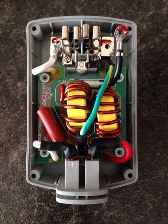
There was for a short tine a five amp version. After examining both version. Only thing I found was a different fuse and a higher price for the 10Amp model. 10Amp, fast blow, 5mmX20mm axial leads, ceramic body. There was a post here a long time ago. Where a member found bad solder joints on the heavy coil leads and re soldering them to the PC board made them operational again.
-
I still have a pair of Access Points in use. You may want to check the date on them. Rev 2.0 and newer are built on the base 2413 PLM board and have the same failed capacitors we see in the 2413S PLM. I had to rebuild a pair myself. The 4 tap/communications builtin test, May give you some added data.
-
I have a few I rebuilt and a spare new one myself.
-
The Insteon web site now says the 2413S serial PLM is discontinued and no longer supported. This should only effect the users still using a ISY994i. InsteonSerial Modem Interface (PLM)This item has been discontinued. Please see our USB Modem Interface.
-
Correct . The Insteon sales site. Says the 2413S PLM is discontinued and no longer available.
-
If I remember correctly. The add on IR Module was needed for the IR module to work. After I got my IR module. UDI had to download something to my ISY994i.
-
A factory reset before installation has fixed issues for some users. Some had test stuff in them and not reset before sales.
-
Bright LED is only one symptom. It can still be bad with a bright LED. Best to do what you thought. Ticket so UDI can help you troubleshoot.
-
Did you power cycle the Eisy also? The PLM is most likely only checked for a boot up. Is the LED on the side of the PLM on at about its normally brightness? Sounds like the PLM has failed or is almost completely failed. How old is it? Sticker on the back should give you information.

