
IndyMike
Members
-
Joined
-
Last visited
Everything posted by IndyMike
-
I'm not aware of any timeout on the Admin Console (or forgot). I simply let it run
-
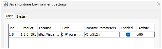
I've been able to leave the event viewer running on my laptop for that long. Longest file I appear to have is 8 days ~122K lines. I've obviously turned off sleep and hibernate (win11). Not sure if it matters, but I increase the java memory allocation to 512M (-Xmx512m parameter). https://wiki.universal-devices.com/index.php?title=Main_Page#Admin_Console_is_very_slow_or_hangs
-
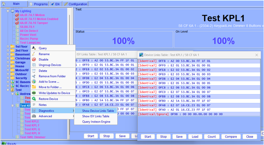
@andrew77 , after seeing your event viewer info, it appears you have 1 - 8 button KPL and 1 SWL relay in your scene. I reconfigured my test setup to be similar (1-8 button KPL + 1 SWL dimmer). Since your devices are sending the correct information to the PLM, and you have excellent communication, that leaves us with a link table problem. This will most likely be in the KPL since the "H" button is not following the SWL. Please perform a "Link table read" by right clicking on the KPL and the selecting "Diagnostics/Show Device Links Table" from the drop down list. See the graphic below. The ISY will take some time communicating with your KPL and will fill in the table on the far right. Once the process is complete, click on the "Compare" button toward to bottom right of the window. In response, the ISY will present a second table showing what it believes "should be" in the KPL link table. It will also highlight any errors. Please perform a screen copy of the tables and post to the forum. iX Address Flag Group Device D1 D2 Button 0 FF8 A2 0 53BC3A FF 1F 01 1 FF0 E2 1 53BC3A 1 00 01 2 FE8 E2 2 53BC3A 1 00 02 3 FE0 E2 3 53BC3A 1 00 03 4 FD8 E2 4 53BC3A 1 00 04 5 FD0 E2 5 53BC3A 1 00 05 6 FC8 E2 6 53BC3A 1 00 06 7 FC0 E2 7 53BC3A 1 00 07 8 FB8 E2 8 53BC3A 1 00 08 9 FB0 A2 5A 53BC3A FF 1F 07 A FA8 E2 7 16CE23 1 00 07 B FA0 A2 1 16CE23 FF 1F 07 C F98 0 0 0 0 00 0 I've created the table above from the data in my KPL. The items at address FA8 and FA0 are what allow the KPL to control and respond to my SWL @16.CE.23 Note: your KPL will likely have far more links. The addresses will be different. Your SWL address is also different @70.65.71. Even so, this information must be there in order for the KPL to control/respond to the SWL. Your KPL should have a record matching the following. The "E2" flag indicates that the KPL is a controller of the listed device (your SWL). The 7 in the last column indicates KPL Button G E2 7 70.65.71 1 00 07 The second link with the "A2" Flag indicates that the KPL is a responder to the listed device. This allows your SWL @70.65.71 to control button G on the KPL. A2 1 70.65.71 FF 1F 07 Assuming things are incorrect, recovery may be as easy as deleting the device from the scene and re-adding. Worst case would be deleting the device and re-linking (painful for a KPL). The reason we are going through this somewhat painful exercise is to determine whether the link table is in fact Incorrect. If so, we'll know how to proceed. The other possibility is that your KPL cannot hear the SWL. We've established that both devices can communicate well with the PLM. That does not guarantee that they can communicate with each other (different phases, etc).
-
It's possible you have a new noisemaker/signal absorber near the PLM. The Holidays are rather famous for these. Try moving your PLM to a different circuit. You can use an extension cord if necessary. If your communications improve, inspect the original circuit for problem devices (UPS, Printers, PC's, chargers). If your communications do not improve, try plugging in a Insteon Lamplinc (or similar) as a helper. If the PLM can't communicate with the LL, it's probably time to go shopping...
-
As @oberkc indicated, your Alexa command is turning on the SWL device ONLY - not the scene. Your KPL button will not change because you are commanding the specific device, not the scene. I an completely Alexa ignorant. I'm assuming there is a way to turn on your Scene rather than the specific SWL device.
-
@andrew77 , thank you for the Log. Your devices are communicating very well. Your SWL @70.65.71 is communicating everything with the PLM correctly. It also has excellent communications (Max Hops =3, Hops Left =3) SWL Switch Off 70.65.71 Group 1 On Tue 01/20/2026 12:32:00 PM : [INST-SRX ] 02 50 70.65.71 00.00.01 CF 11 00 LTONRR (00) Tue 01/20/2026 12:32:00 PM : [Std-Group ] 70.65.71-->Group=1, Max Hops=3, Hops Left=3 SWL to PLM Group Cleanup SWL @ 70.65.71 Issuing cleanup to PLM @71.1B.2E Tue 01/20/2026 12:32:00 PM : [INST-SRX ] 02 50 70.65.71 71.1B.2E 40 11 01 LTONRR (01) Tue 01/20/2026 12:32:00 PM : [Std-Cleanup ] 70.65.71-->ISY/PLM Group=1, Max Hops=0, Hops Left=0 SWL Switch 70.65.71 Group 1 Off Tue 01/20/2026 12:32:11 PM : [INST-SRX ] 02 50 70.65.71 00.00.01 CF 13 00 LTOFFRR(00) Tue 01/20/2026 12:32:11 PM : [Std-Group ] 70.65.71-->Group=1, Max Hops=3, Hops Left=3 SWL to PLM Group Cleanup SWL @ 70.65.71 Issuing cleanup to PLM @71.1B.2E Tue 01/20/2026 12:32:11 PM : [INST-SRX ] 02 50 70.65.71 71.1B.2E 45 13 01 LTOFFRR(01) Tue 01/20/2026 12:32:11 PM : [Std-Cleanup ] 70.65.71-->ISY/PLM Group=1, Max Hops=1, Hops Left=1 Your Alexa command was processed correctly. However, it was directed to the SWL @71.1B.2E, not your scene. This command will only turn on that specific device. Alexa (Rest) SWL Command ON Alexa turning device 07.65.71 On Tue 01/20/2026 12:32:26 PM : Create REST U7 [/rest/nodes/70%2065%2071%201/cmd/DON] Tue 01/20/2026 12:32:26 PM : U7 Rest: submitCmd([70 65 71 1],[DON],[<NULL>]) Tue 01/20/2026 12:32:26 PM : [INST-TX-I1 ] 02 62 70 65 71 0F 11 FF Tue 01/20/2026 12:32:26 PM : [INST-ACK ] 02 62 70.65.71 0F 11 FF 06 LTONRR (FF) Tue 01/20/2026 12:32:26 PM : [INST-SRX ] 02 50 70.65.71 71.1B.2E 2F 11 FF LTONRR (FF) Tue 01/20/2026 12:32:26 PM : [Std-Direct Ack] 70.65.71-->ISY/PLM Group=0, Max Hops=3, Hops Left=3 Your KPL button appears to be button "G" on an 8 button KPL (group 7). It also performed correctly in communicating to the PLM and had excellent communications (Max Hops=3, Hops Left=3). KPL Button H On - 8 button KPL turning on group 7 KPL Button G @70.9C.CE Tue 01/20/2026 12:33:48 PM : [INST-SRX ] 02 50 70.9C.CE 00.00.07 CF 11 00 LTONRR (00) Tue 01/20/2026 12:33:48 PM : [Std-Group ] 70.9C.CE-->Group=7, Max Hops=3, Hops Left=3 KPL Button G to PLM Group Cleanup Tue 01/20/2026 12:33:49 PM : [INST-SRX ] 02 50 70.9C.CE 71.1B.2E 4A 11 07 LTONRR (07) Tue 01/20/2026 12:33:49 PM : [Std-Cleanup ] 70.9C.CE-->ISY/PLM Group=7, Max Hops=2, Hops Left=2 In summary, your devices appear to be communicating correctly and well with the PLM. While it's possible that your SWL isn't communicating well with your KPL, that's unlikely. My guess would be that you have a link table error in one or both of your devices. Could your post The scene that you are using for these devices? It should look something like the following. Failing a scene membership issue, we'll need to look at the link tables in the devices themselves. We'll leave that for another post...

-
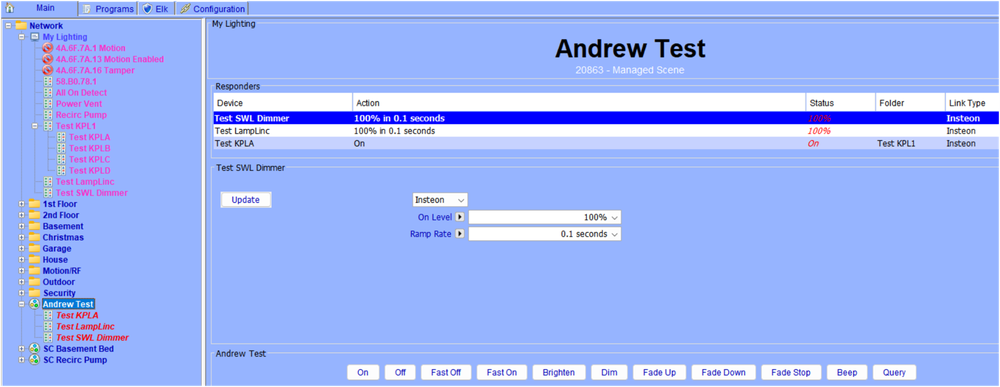
@andrew77 , my go to for troubleshooting problems of this nature is using the Event Viewer on Level 3. I generated a test Scene that contains a KPL, LampLinc, and a SWL Dimmer. All 3 devices are controllers. Any of the 3 devices will turn the scene On/Off and the KPL Button "A" will track the On/Off. I did this to show you what you "should" be seeing in the event viewer when you activate the scene devices. If you think you are seeing something different, you likely have a device link table error or communication issues. Post back and we can work through those. When you activate a "Device" in a scene it should communicate with group members through Group 01 (for simple devices) or Groups 1 - 8 for KPL's. This will show up in the event viewer as shown below. Request a group cleanup from group members to verify they received the command. This includes your PLM. In the following I am showing addresses for my devices: 16.CE.23 is my SWL Dimmer (your dimmer address will be different. The Group # 00.00.01 should be present in your event viewer. My PLM is at Address 53.BC.3A (yours will obviously be different). The group 1 cleanup commands between your device and your PLM should be present. I used KPL button "A" as the controller for my Scene (6 button mode). This works out to be group 3 when the device activates the scene. If you use a different button (or are using 8 button mode) the group # will be different. TAP SWL Dimmer Off (Superfluous ISY Information Dim) SWL Dimmer @16.CE.23 Turning Group 1 off Tue 01/20/2026 09:23:33 AM : [INST-SRX ] 02 50 16.CE.23 00.00.01 CB 13 00 LTOFFRR(00) Tue 01/20/2026 09:23:33 AM : [Std-Group ] 16.CE.23-->Group=1, Max Hops=3, Hops Left=2 Tue 01/20/2026 09:23:33 AM : [D2D EVENT ] Event [16 CE 23 1] [DOF] [0] uom=0 prec=-1 Tue 01/20/2026 09:23:33 AM : [ 16 CE 23 1] DOF 0 Tue 01/20/2026 09:23:33 AM : [D2D EVENT ] Event [16 CE 23 1] [ST] [0] uom=100 prec=0 Tue 01/20/2026 09:23:33 AM : [ 16 CE 23 1] ST 0 (uom=100 prec=0) Tue 01/20/2026 09:23:33 AM : [D2D EVENT ] Event [18 93 83 1] [ST] [0] uom=100 prec=0 Tue 01/20/2026 09:23:33 AM : [ 18 93 83 1] ST 0 (uom=100 prec=0) Tue 01/20/2026 09:23:33 AM : [D2D EVENT ] Event [19 21 5C 3] [ST] [0] uom=100 prec=0 Tue 01/20/2026 09:23:33 AM : [ 19 21 5C 3] ST 0 (uom=100 prec=0) SWL Dimmer @16.CE.23 Requesting PLM Cleanup @53.BC.3A Tue 01/20/2026 09:23:33 AM : [INST-SRX ] 02 50 16.CE.23 53.BC.3A 41 13 01 LTOFFRR(01) Tue 01/20/2026 09:23:33 AM : [Std-Cleanup ] 16.CE.23-->ISY/PLM Group=1, Max Hops=1, Hops Left=0 Tap SWL Dimmer On (Superfluous ISY Information Removed) SWL Dimmer @16.CE.23 Turning Group 1 on Tue 01/20/2026 09:24:23 AM : [INST-SRX ] 02 50 16.CE.23 00.00.01 CB 11 00 LTONRR (00) Tue 01/20/2026 09:24:23 AM : [Std-Group ] 16.CE.23-->Group=1, Max Hops=3, Hops Left=2 SWL Dimmer @16.CE.23 Performing cleanup on PLM@53.BC.3A Tue 01/20/2026 09:24:23 AM : [INST-SRX ] 02 50 16.CE.23 53.BC.3A 46 11 01 LTONRR (01) Tue 01/20/2026 09:24:23 AM : [Std-Cleanup ] 16.CE.23-->ISY/PLM Group=1, Max Hops=2, Hops Left=1 LampLinc On Lamplinc On @18.93.83 turning Group 1 On Tue 01/20/2026 09:31:09 AM : [INST-SRX ] 02 50 18.93.83 00.00.01 CF 11 00 LTONRR (00) Tue 01/20/2026 09:31:09 AM : [Std-Group ] 18.93.83-->Group=1, Max Hops=3, Hops Left=3 Lamplinc On @18.93.83 Requesting PLM Cleanup @53.BC.3A Tue 01/20/2026 09:31:09 AM : [INST-SRX ] 02 50 18.93.83 53.BC.3A 4A 11 01 LTONRR (01) Tue 01/20/2026 09:31:09 AM : [Std-Cleanup ] 18.93.83-->ISY/PLM Group=1, Max Hops=2, Hops Left=2 Lamplinc Off Lamplinc Off @18.93.83 turning Group 1 Off Tue 01/20/2026 09:36:20 AM : [INST-SRX ] 02 50 18.93.83 00.00.01 CF 13 00 LTOFFRR(00) Tue 01/20/2026 09:36:20 AM : [Std-Group ] 18.93.83-->Group=1, Max Hops=3, Hops Left=3 Lamplinc Off @18.93.83 Requesting PLM Cleanup @53.BC.3A Tue 01/20/2026 09:36:20 AM : [INST-SRX ] 02 50 18.93.83 53.BC.3A 45 13 01 LTOFFRR(01) Tue 01/20/2026 09:36:20 AM : [Std-Cleanup ] 18.93.83-->ISY/PLM Group=1, Max Hops=1, Hops Left=1 KPL Button "A" Off KPL @19.21.5C turning Group 3 (KPL Button A) Off Tue 01/20/2026 09:38:09 AM : [INST-SRX ] 02 50 19.21.5C 00.00.03 CF 11 00 LTONRR (00) Tue 01/20/2026 09:38:09 AM : [Std-Group ] 19.21.5C-->Group=3, Max Hops=3, Hops Left=3 Button "A" Off @19.21.5C Requesting PLM Cleanup @53.BC.3A Tue 01/20/2026 09:38:09 AM : [INST-SRX ] 02 50 19.21.5C 53.BC.3A 45 11 03 LTONRR (03) Tue 01/20/2026 09:38:09 AM : [Std-Cleanup ] 19.21.5C-->ISY/PLM Group=3, Max Hops=1, Hops Left=1
-
Using a device to trigger a program that in turn sends commands back to the trigger device, has been documented to cause collisions that can produce all-on/all-off events. In short, it's an ISY no-no. The 3 second delay that I show in my program is intended to eliminate the collisions. https://wiki.universal-devices.com/index.php?title=INSTEON_Random_All_On_Events If you want to eliminate the program delays, I would suggest 2 separate KPL buttons controlling 2 separate scenes: KPL button 1/scene 1. KPL button 1 is a "Non-Toggle" On button that is controller for your scene 1. It will ONLY send "on" commands to the scene. Include KPL button 2 in this scene as a responder. KPL button 2/scene 2. KPL button 2 is a "Non-Toggle" Off button that is controller for your scene 2. If will ONLY send "off" commands to the scene. Include KPL button 1 in this scene as a responder. This should eliminate the delays associated with programs while also preventing communication problems. You can access the KPL "Buttons Toggle Mode" at the buttom of your KPL screen in the Admin Console. I have many instances where I use the Non-Toggle [off] on KPL's. I use them as monitors around the house (Outside, basement, 1st floor, 2nd floor and House). If the button is ON, pushing it sends an Off to all scene members (1st floor as an example). Helps when I leave something on in the basement and I'm going to bed. I can hit a button on my bedroom KPL rather than "running the stairs".

-
@andrew77 , the SWL and Lamplinc also need to be CONTROLERS of the scene. If they are Responders, they will not send the On/Off/Dim commands to other scene members.
-
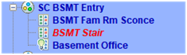
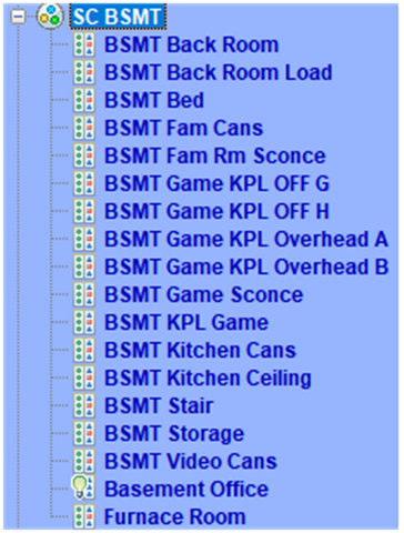
@scholarwarrior , what you are describing should work. I use something similar for my basement office that is controlled by a SWL Dimmer on the stairs. The SWL dimmer is the controller for the scene BSMT Entry. When turned on scene members BSMT Fam Sconce and BSMT Office activate. When I exit the basement I turn off the SWL dimmer which turns off the same two scene members. The SWL OFF also triggers a program that turns off the BSMT Scene. The 3 second wait is to prevent collisions between the ISY and scene cleanup requests being sent by the SWL Dimmer. BSMT Off - [ID 0009][Parent 0004] If 'Basement / BSMT Stair' is switched Off Then Wait 3 seconds Set 'Basement / SC BSMT' Off Else - No Actions - (To add one, press 'Action')
-
I hope things work out for you. I learned/re-learned a number of things going through the process. That's a good day for an old guy. I can't comment on the Hubitat interface - No experience there. Home Assistant was extremely unfriendly back in 2020 when I started with Z-wave. It has improved a lot since then. The Z-wave mapping/healing/manual routing capabilities are very beneficial. The Home Assistant interface to the ISY is excellent. It allowed me to bridge the ISY/Insteon system to HA, melding the two systems (thanks to @shbatm and @bdraco). I use it extensively. I've been using the ISY (26)/insteon since both started. I really can't separate the two since Insteon is nothing without an ISY. I began moving to Z-wave and Zigbee when Smartlabs shut down in 2022. I'll agree that the Insteon solution for lighting and scenes was excellent, but I will not be going back. Their price point combined with their single source nature makes them unappealing. I have a quantity of spare Insteon KPL's that I am coveting (I love these). Everything else gets replaced with Z-wave as attrition takes it's toll. As far as never ending projects are concerned, I prefer to call them Hobbies. My better half agrees - refers to me as her hobby.
-
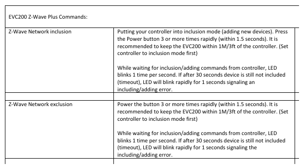
@raydoc , looks like you previously had an ISY994. That being the case, the EISY should be able to find your EVC200 ASSUMING it's in range. Unfortunately the valve appears to be "z-wave plus" or z-wave 500 series. Not the best for range and very difficult if you don't have a robust mesh. Newer 700/800 series devices are greatly improved. Since you obviously can't move your valve closer to the EISY, try moving the EISY close to the valve as shown in the users manual below. You should absolutely try excluding the valve 1st since previous excludes will not have worked with the EISY out of range.
-
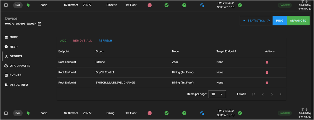
@TomNow2 , managed to learn a few things (or re-learn) about direct association. It's been a few years since I last tried it. It was a little painful, but in the end it worked well. As I mentioned above, OTA firmware updates will absolutely break associations. Bit me again - caused me to use some bad words. Devices being associated MUST have the same security level - Bite #2. Certain Zooz devices cannot be used without a load. The ZEN76 and ZEN77 dimmers apparently use current sensing as part of their dimming scheme - totally fouls things up when used without a load - Bite #3. Bad word usage again. Your ZEN72 dimmers are listed as no load compatible. https://www.support.zboxhub.com/kb/article/1737-how-to-use-zooz-switches-without-a-load/ Devices must have the same security level - this part I managed to remember. In the end I was able to associate a ZEN77 load connected dimmer with - a ZEN71 switch (on/off), ZEN32 scene controller (On/off, Bright/Dim), and a ZEN77 load connected dimmer (On/Off, Bright/Dim). All devices operated seamlessly with very little delay. Associations for the ZEN77 shown in the graphic below. This is a Home Assistant presentation - hopefully it will translate to Hubitat. The Lifeline association is from the switch to the Hub (all units should have this). The On/Off and Multilevel change associations are required to give "Insteon like" On/Off and dimming control. This actually worked far better than I remembered. There may have been improvements since I last tried things. Target device On level settings - Things didn't seem to synch well until I set the target to 100% on level in settings. Default was previous brightness Notes - the Zen77 devices were using security level S0. This may speed things up. Using two slaves would present far more associations and settings variables. This is where UD's Insteon scene setting shine. They've made things very easy for us. I have no experience with Hubitat. Not sure if there are limitations there. Bottom line - it was far more work getting the z-wave direct association working than anything I've used with the ISY994/Insteon. Once setup, it worked very well and was very responsive. I saw your posts on the Hubitat forum. You don't appear to be the type of person that throws in the towel easily...

-
@Techman , that is THE Insteon all-off command. If your devices didn't respond they are newer and have had the command removed. The same devices should not respond to an All-on. I'd say it's working. You can try turning on the "ISY Scene" to see which of your devices respond to an "All-On". All linked devices On (group FF): 02 62 00 00 FF CF 11 00 All linked devices Fast On group FF): 02 62 00 00 FF CF 12 00
-
@TomNow2 , read through your posts over at Hubitat. If I understand correctly you are using Z-wave Direct Association between your dimmers to construct an N-Way setup. I've tried that in the past with mixed results but I was using dimmers at opposite ends of my house. One of the things that tripped my up was that OTA firmware updates would break the association. You need to exclude/include devices after an update and then re-associate. I eventually went back to traditional Hub operated scenes which work well (HA). One thing that I did see in your post was that you were trying to "adjust" the dimming level using a slave. Assuming you are using LED bulbs I could see where that might be an issue. The LED dimming curve is non-linear and by the time you see a response in the bulb, you've typically overshot your desired setpoint. Any communication delays will exasperate the issue (you effectively have a bow wave of bright/dim commands in queue). Rather than trying to actively adjust the dimming level, you could use the double and triple tap controls to define scenes with the levels you desire. If doing so, I would eliminate the direct association and program the scenes in the Hub. I will admit that scene control is one of the areas where Insteon excels. I would be surprised if the Innovelli dimmers perform differently in the same configuration. I have a couple of areas where I could add a virtual 3 way rather easily. I'm also curious. I'll take a swing at some configurations and let you know if I learn anything.
-
OK, I understand why the response isn't immediate, but it's surprising that you notice a measurable delay. What specific switches are you using (Zen77, etc) and what type of Z-wave controller (I'm not up on Hubitat). To put things in perspective, I've been moving from Insteon (ISY994) to Z-wave (Home Assistant). I have numerous locations where I have Insteon/Z-wave switches controlling each other. This is a Virtual 3-way from the ISY994 to Home Assistant. I don't notice a delay. Insteon Switch >>>>> ISY994 >>>>> Network >>>> Home Assistant >>>> Zooz Dimmer. Not sure if you have a Hubitat problem or a Slave Switch problem
-
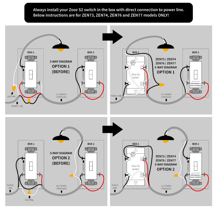
@TomNow2 , I'm a bit late to the party and I'm confused by the delay that you are seeing with the Zooz switches. Zooz is one of the few manufacturers that allows you to combine their Z-wave switch/dimmer with a conventional mechanical switch. It's one of the reasons I've installed them. In my experience, the Zooz direct wire is far faster (immediate), 100% reliable, and far less expensive than the Insteon "virtual" 3-way. The Zooz direct wire install (below) should be immediate. You mentioned "slave" switches - I assume these are simple mechanical switches. There should not be any interaction with the hub. If actuating the mechanical switch doesn't produce an immediate response in the load, you may have a ramp rate or something else programmed in the Z-wave switch.
-
@Techman , give it a try (the ISY994 doesn't have the "isy scene" or I would try it). Open the event viewer to level 3 and execute your program containing the "ISY scene off". If you see "02 62 00 00 FF CF 13 00" appear in the viewer you have sent an "all off" to all linked Insteon devices. Be advised that there may be follow on commands turning off Z-wave and other devices. My read is that this is an "ISY world off" command. If you learn differently, please advise.
-
@Techman - on my ISY994 this is the same as setting "My Lighting" to off programmatically. It generates identical commands in the event viewer.
-
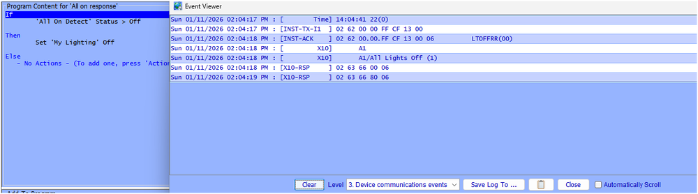
@Techman , I use a program to monitor (query) a lamplinc that is my dedicated "all-on" detector. If the Lamplinc is detected as "ON" event has occurred and a "my Lighting" off program is called. You could easily construct a similar program and Link it to a KPL button - activate if "All-On" Note: setting "My lighting Off" turns will issue the Group FF off command to all Insteon devices. On my system, it also issues an X10 all lights off to housecode A (see event viewer below). I don't have Z-wave installed but these could also be turned off as well. If you don't want "other technology" devices turned off, you would be better served by creating an "all off" scene as others have indicated. Disclaimer - this is on the ISY994 Query Lamplinc every 5 Min All on Poll - [ID 000A][Parent 0013][Run At Startup] If Time is Last Run Time for 'All on Poll' + 5 minutes Then Set 'All On Detect' Query Else - No Actions - (To add one, press 'Action')Call My Lighting Off if Lamplinc is ON All on response - [ID 0011][Parent 0013] If 'All On Detect' Status > Off Then Set 'My Lighting' Off Else - No Actions - (To add one, press 'Action')Event Viewer for "My Lighting OFF" Sun 01/11/2026 09:07:37 AM : [ Time] 09:07:37 22(0) Sun 01/11/2026 09:07:37 AM : [INST-TX-I1 ] 02 62 00 00 FF CF 13 00 Sun 01/11/2026 09:07:38 AM : [INST-ACK ] 02 62 00.00.FF CF 13 00 06 LTOFFRR(00) Sun 01/11/2026 09:07:38 AM : [ X10] A1 Sun 01/11/2026 09:07:38 AM : [ X10] A1/All Lights Off (1)
-
Thanks Brian. I should have noticed that the relay in the schematic was 120V. Miss on my part. Based on the date codes, my Icon was made about 3 months after @johnmsch 's togglelinc. Hopefully they're the same layout. Would you happen to have a better schematic of the Relay/dimmer versions in this Vintage? Understand if that is constrained by a NDA.
-
As @lilyoyo1 indicated, some Z-wave devices have features that (if set incorrectly) can overwhelm the system with excessive communication. I purchased 4 Zooz ZEN04 power monitoring plugs for monitoring/shutting down various TV and appliances. They worked well in most locations after setting the parameters for monitoring power. My Sony TV did NOT play well with the device regardless of the parameter settings. The communication would hit levels that would cause the system to become sluggish. Disabling monitoring instantly returned the system to normal. I communicated the problem to Zooz and they rolled out a firmware update with additional tuning options. The result is shown in the second plot. System performance is night and day different. I am still running this system today. As both @oberkc and @lilyoyo1 have indicated, consult your logs to determine if you have a device that is constantly communicating and using up all the bandwidth in your system.
-
Thanks, that produced a spontaneous laugh. I needed that today.
-
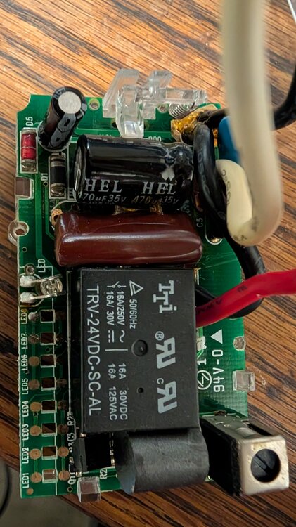
Update - the app note I posted above is a bit misleading. It is in fact what the older Insteon supplies were "modeled" after. However the Insteon version regulated at 30V (not 5v as is the App note). The attached schematic was developed by jbauer back in 2006. As noted, the schematic is not complete. I found one of my malfunctioning ICON relay units from 2006 (photo's below). I had noted that the unit "cycled" when I pulled it. Unit powered up OK without a load. I disassembled and verified the supply regulated @30V as jbauer had documented. My unit had an additional MOV (SDS 201KD07) across the power input (201V threshold). The C2 470u cap appeared to be in good condition as did the D1 30V zener diode. C1 is the large brown (Mica?) cap. I would not expect this to degrade.

-
Your 3 way switches are "virtual", meaning that only one is actually connected to the load. The other switch simply communicates with the load connected switch to turn your lights on. Bottom line, you only "have" to replace the load connected switch. I3, relay, your choice. .... Or you could swap your current dimmers to see if the triac is dying on the current one connected to the load. I have a number of dimmers that have dead triac outputs - just use them for communicating "ON/OFF" commands to other devices.


