
evilpete
Members
-
Joined
-
Last visited
-
Are there any Zigbee buttons that work or "supported" ??
-
Please include: Manufacturer Name : ONENUO / IHSENO Model # : 22WYZ Link to sales/availability site(s): https://www.amazon.com/IHSENO-ZigBee3-0-Remote-Button-Zigbee/dp/B0CCCKKH27/?th=1 https://www.aliexpress.com/i/3256809496235355.html Key/desired function support Report DON/OFF events described in NodeDef but missing in NodeInfo NodeInfo: <nodeInfo> <node flag="128" nodeDefId="ZB05836_001_1"> <address>ZB05836_001_1</address> <name>ZB 5836.1 On-Off W Button</name> <family>14</family> <hint>39.0.0.13</hint> <parent type="3">26264</parent> <type>255.1.255.255</type> <enabled>true</enabled> <deviceClass>0</deviceClass> <wattage>0</wattage> <dcPeriod>0</dcPeriod> <startDelay>0</startDelay> <endDelay>0</endDelay> <pnode>ZB05836_001_1</pnode> <rpnode>ZB05836_001_1</rpnode> <sgid>1</sgid> <typeInfo> <t val="103" id="ioxType"/> <t val="4742" id="mfgCode"/> <t val="SNZB-01" id="model"/> </typeInfo> </node> <properties/> </nodeInfo>NodeDef <nodeDefs> <nodedef nls="103" id="ZB05836_001_1"> <sts> <st hide="T" editor="ZB_ERR" id="ERR"/> </sts> <cmds> <sends> <cmd id="DON"/> <cmd id="DOF"/> </sends> <accepts> <cmd id="IDENTIFY"> <p optional="T" editor="ZB_IDENTIFY" id=""/> </cmd> <cmd id="QUERY"/> </accepts> </cmds> </nodedef> </nodeDefs>
-
I'm familiar with the hints described in hint.yaml file on GitHub, but is there a more complete list available somewhere? For example, I have a Zwave switch, which was assigned hint "4.16.0.0" a value not described in the document.. Other hints: Zwave switch :0.0.0.48 Zwave plug : 10.0.0.0 Zigbee plug: 10.0.0.0 Zwave : 48.32.50.53 37.45.61.165 Zigbee On-Off Switch: 48.32.50.53 Zigbee button: 39.0.0.13
-
Q: should we put together a list on the wiki of functional and nonfunctional zig devices?
-
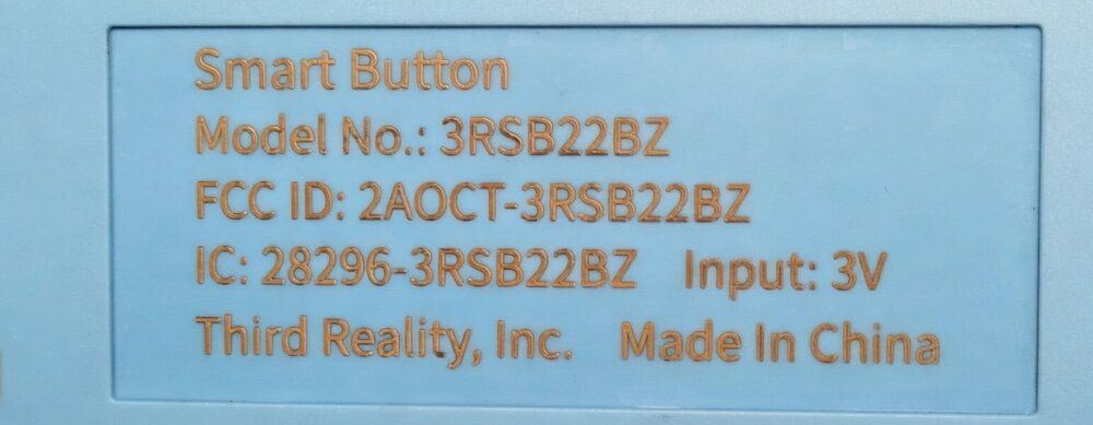
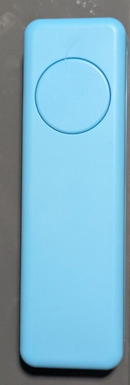
THIRDREALITY ZigBee Smart Button Model # 3RSB22BZ https://www.amazon.com/dp/B0BJDWR3BC?th=1 Receive process button event. IoX v6.0.0 I am willing send capture log and/or buy/donate a unit if it will help
-
Can you give a pros/cons review? This is something I've been thinking about recently
-
I was able to link my Gen 4 Nest thermostat using the pairing code I got the pairing code though Google's "Home" App (Google Home App -> Thermostat -> Gear Icon -> Device Information -> Linked Matter Apps & Services -> Link Apps and Services -> Use pairing code) then added it using the UD Mobile app (Settings -> Matter -> Add Matter with Setup code) After a minute or so, the device was added, unfortunately only as a 'On-Off Switch' (the thermostat does respond to the On-Off commands) According to sources temperature and fan control are available <nodeDefs> <nodedef nls="103" id="ZM00002_001_1"> <sts> <st editor="ZM_OFF_ON_UNKNOWN" id="ST"/> <st hide="T" editor="ZM_ERR" id="ERR"/> </sts> <cmds> <sends/> <accepts> <cmd id="DON"> <p optional="T" editor="ZM_0_100_PERCENT" init="ST" id=""/> </cmd> <cmd id="DOF"/> <cmd id="TOGGLE"/> <cmd id="QUERY"/> </accepts> </cmds> </nodedef> </nodeDefs> <nodeInfo> <node flag="128" nodeDefId="ZM00002_001_1"> <address>ZM00002_001_1</address> <name>ZM 002.1 On-Off Switch</name> <family>15</family> <hint>48.32.50.53</hint> <type>255.1.255.255</type> <enabled>true</enabled> <deviceClass>0</deviceClass> <wattage>0</wattage> <dcPeriod>0</dcPeriod> <startDelay>0</startDelay> <endDelay>0</endDelay> <pnode>ZM00002_001_1</pnode> <rpnode>ZM00002_001_1</rpnode> <typeInfo> <t val="103" id="ioxType"/> <t val="0" id="mfgCode"/> <t val="" id="model"/> </typeInfo> <property name="" uom="78" formatted="On" value="100" id="ST"/> </node> <properties> <property name="" uom="78" formatted="On" value="100" id="ST"/> </properties> </nodeInfo>
-
Third reality zigbee smart plug power monitoring not showing up Third Reality, Inc Model # 3RSP02028BZ https://www.amazon.com/THIRDREALITY-Zigbee-Smart-Plug/dp/B0BPY2KRHH IoX v.5.9.1 The device has no problem pairing, and is functional with on / off capabilities, but the power monitoring feature is not available. Note: under Xray: Device channel database object: ELECTRICAL_MEASUREMENT is listed
-
on my Ipad when I create a favorite the default note color is #71A6FA, I've noticed that if I change the color and then change it back to the value #71A6FA it's not the same. To reproduce add a new node to favorites, change the default color (eg: #71A6AA) then change it back to #71A6FA
-
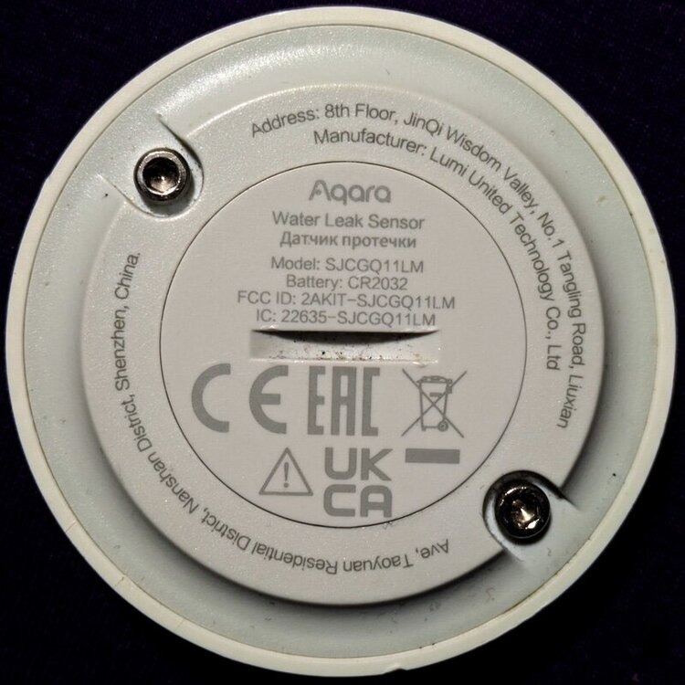
Name: Aqara Water Leak Sensor URL: https://www.amazon.com/dp/B07D39MSZS I'd like this also, I have one and it connects but the note identifies itself as "main" with no attributes
-
Understood.. On a simular topic, it's already been noted that iOS and android backups are not compatible, but a way to export/import just favorites would be very convenient for copying "consoles" between device devices (and hopefully easier to implement 😀) btw: android should not even be allowed to import an iOS backup, it really fuckers the android app, requiring a purge and then reinstall (and a lesson turned)....
-
I placed a cheap ($11) usb fan from Amazon on top on the unit have had zero problems With the ambient temperature on my desk is around 71° [admin@eisy ~]$ ./get-temp.sh CPU0 26 C / 78 F CPU1 27 C / 80 F CPU2 26 C / 78 F CPU3 27 C / 80 F TZ0 27 C / 80 F Quiet 90mm Router Fan Cooler $11.99 2Pack Quiet 80mm USB Fan Dual-Ball Bearings $19.99
-
Is there a way to copy the advanced configuration settings in favorites one object node to another, for example, value based color settings on multiple temperature sensors.
-
Yeah, now that i understand what is going on more that's what I've thinking about with a few translation table based on protocol number... I was trying to use it as it at first not realizing it was special case mostly for Tasmota integrations
-
@sjenkins thanks I'll probably have to write a plug-in that interprets the output of rtl-433. it's written in C and the code focuses on SDR protocol decoding thus the input format is not gonna change (I contributed to code base a few years ago) after looking around they have some example code that does something similar for another product. Side Note: once done it will be trivial to incorporate pre-existing devices as input sensors Tire pressure: {"time" : "2025-08-04 18:22:45", "protocol" : 186, "model" : "Hyundai-VDO", "type" : "TPMS", "id" : "5173f60b", "state" : 48, "flags" : 8, "repeat" : 1, "pressure_kPa" : 248.875, "temperature_C" : 25.000, "maybe_battery" : 1, "mic" : "CRC"} Home security sensors (admittedly the neighbors') {"time" : "2025-06-30 22:14:47", "model" : "Interlogix-Security", "subtype" : "unknown", "id" : "51a4c2", "battery_ok" : 0, "switch1" : "CLOSED", "switch2" : "CLOSED", "switch3" : "OPEN", "switch4" : "CLOSED", "switch5" : "CLOSED", "raw_message" : "d24000"} Efergy home energy meter (also the neighbors', but hey, it's good for development input data) {"time" : "2025-07-31 19:01:36", "protocol" : 100, "model" : "Efergy-e2CT", "id" : 16386, "battery_ok" : 0, "current" : 18.781, "interval" : 6} Rolling code Keyfobs {"time" : "@0.843604s", "protocol" : 164, "model" : "Secplus-v2", "id" : 1959100928, "button_id" : 16, "remote_id" : 1959100928, "fixed" : "70678577664", "rolling" : "240124739"} Motion sensors {time" : "2024-09-27 19:28:26", "model" : "Skylink motion sensor", "motion" : "true", "id" : "1e3e8", "raw" : "be3e8"}


