IndyMike
Members
-
Joined
-
Last visited
Everything posted by IndyMike
-
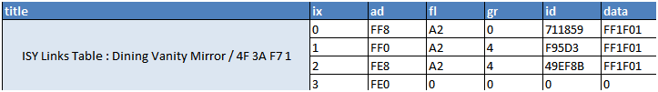
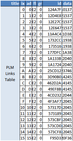
@NewB , Suffice it to say that things have gotten a bit hosed (technical term). The PLM links table you posted is extremely short (21 entries). The PLM is listed as the controller for all the devices in the ID column. There are no scenes listed. It is possible that the PLM read process was interrupted. Try this a couple of times to see if you get the same result. If so, proceed with the "recovery below". The device table you posted indicates that the "Dining Vanity Mirror" is a Responder to the devices listed in the ID Column. It can't control anything. Recovery: Please verify that your PLM address is 71.18.59. Since your PLM link table is incorrect (after multiple PLM restores), you'll need to perform an ISY restore. LOOK at your backup file sizes. If you have a recent backup that is significantly different in size (from previous), it's suspect. Choose a recent backup that looks consistent. If you get socket errors during the restore (or a backup), do not trust it. Logout of the admin console, clear the cache, log back in and restart the process. When the restore ISY complete correctly, it will reboot the ISY. Log back in, turn off "writes to battery devices", and perform a "Restore Modem". This should re-write the PLM records. After the above completes, re-check your PLM records. If it's still very low (<100) post back and we'll rethink things. It's possible that that the ISY will not re-write the device link tables in step 3 (if it didn't detect a PLM change). The Only way to know for sure is to perform "link table read/compare's" on devices. You can address these individually by running a "device restore", but if there are many, it's may be easier to use the "restore devices" from the file menu.
-
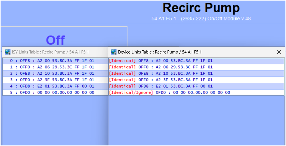
The ISY is still sending a group 12 Off command that may be affecting things. A program is being triggered because of your "scene test". Likely not the cause of everything failing, but it's definitely complicating things. Can you open the event viewer on level 3 and perform "Link Table Read" on "Dining Vanity Mirror (4F 3A F7 1)"? Copy the event viewer to the clipboard and paste to the forum. Please also post the contents of the Link table. I'm curious if you are getting Nack responses. The following are examples of the event viewer and link tables for one of my simpler devices. I've edited the event viewer to show only the 1st two link table reads. Sat 04/04/2026 09:48:19 AM : [INST-TX-I2CS] 02 62 54 A1 F5 1F 2F 00 00 00 0F FF 01 00 00 00 00 00 00 00 00 C2 Sat 04/04/2026 09:48:19 AM : [INST-ACK ] 02 62 54.A1.F5 1F 2F 00 00 00 0F FF 01 00 00 00 00 00 00 00 00 C2 06 (00) Sat 04/04/2026 09:48:20 AM : [INST-SRX ] 02 50 54.A1.F5 53.BC.3A 2F 2F 00 (00) Sat 04/04/2026 09:48:20 AM : [Std-Direct Ack] 54.A1.F5-->ISY/PLM Group=0, Max Hops=3, Hops Left=3 Sat 04/04/2026 09:48:20 AM : [INST-ERX ] 02 51 54 A1 F5 53 BC 3A 15 2F 00 00 01 0F FF 00 A2 00 53 BC 3A FF 1F 01 B8 Sat 04/04/2026 09:48:20 AM : [Ext-Direct ] 54.A1.F5-->ISY/PLM Group=0, Max Hops=1, Hops Left=1 Sat 04/04/2026 09:48:20 AM : [INST-TX-I2CS] 02 62 54 A1 F5 1F 2F 00 00 00 0F F7 01 00 00 00 00 00 00 00 00 CA Sat 04/04/2026 09:48:20 AM : [INST-ACK ] 02 62 54.A1.F5 1F 2F 00 00 00 0F F7 01 00 00 00 00 00 00 00 00 CA 06 (00) Sat 04/04/2026 09:48:21 AM : [INST-SRX ] 02 50 54.A1.F5 53.BC.3A 2F 2F 00 (00) Sat 04/04/2026 09:48:21 AM : [Std-Direct Ack] 54.A1.F5-->ISY/PLM Group=0, Max Hops=3, Hops Left=3 Sat 04/04/2026 09:48:21 AM : [INST-ERX ] 02 51 54 A1 F5 53 BC 3A 15 2F 00 00 01 0F F7 00 A2 06 29 53 3C FF 1F 01 4B Sat 04/04/2026 09:48:21 AM : [Ext-Direct ] 54.A1.F5-->ISY/PLM Group=0, Max Hops=1, Hops Left=1
-
Hey @NewB , The "scene test" is a nice tool, but is has some limitations. If there is activity on the powerline (motion sensors, devices activating) or Programs executing on the ISY, the PLM will exit the test. The red communication above looks like an ISY program ran and turned off group 13. It's generally best to disable programs to get consistent results. The communication above shows the ISY trying to write link records to the device @11.96.2A. The write operation times out because the device is not responding. This device should be tagged with the green "1011" in the admin console. The device isn't part of the scene that you tested, but if you have other devices with pending writes it indicates they do not have all of their links (scenes). Try resolving the pending writes to see if things resolve.
-
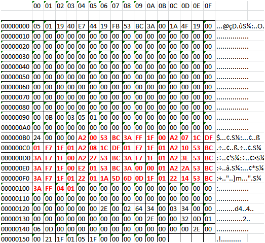
@pinlawr , Interesting that you are seeing the .Rec files reset on devices where you are writing parameter changes. Very curious if your program delay helps reduce or eliminate the problem. Unfortunately, copying a .REC file from one device to another will not completely resolve the problem. The REC file is a binary memory map for the specific device. When you copied the REC file to the missing device you also copied all of the source device's settings and scene members. The following is a REC file from one of my Switchlincs viewed in Hex. The items in Red are the link table contents for the device.
-
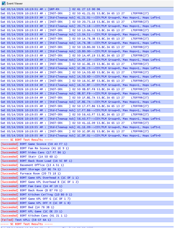
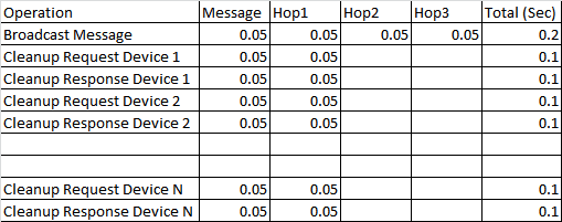
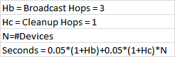
If you are using your KPL button as a "Non-toggle OFF", you shouldn't need to worry about the individual devices On level. You may want to adjust ramp rates. A couple of differences in how "scenes" are implemented for devices vs the ISY: The ISY will execute a scene with no follow-up. It does not verify that devices heard or responded to the scene command (it assumes). Insteon devices will execute "cleanup" requests to each scene member to determine whether the command was received/executed. The device may retry commands. This is really very reliable. The upshot here is that Large scenes require a LOT of communication and significant time. If another device begins transmitting in the middle of this process the device can/may abort the verification. With this in mind, you want to prevent programs from being triggered by the all-off and jumping in during the verification process. Broadcast "All Link" messages are standardized at 3 Hops. Cleanup requests/responses use 1 Hop. Each standard length message (or hop) requires 0.05 Seconds. The table below shows how this can quickly add up. I have a 17 device basement scene that requires 0.2 seconds when executed by the ISY (no cleanups). It requires 3.4 seconds when operated from my KPL. Once you have your scene configured, you can test the operating (to a degree) by using the ISY scene test function. The scene test will turn all of the scene devices ON using an Insteon standard message (02 62) to your scene (no verification). If will then turn the scene on using the Insteon "All Link Command" (02 61) to the scene. The PLM will then interrogate each scene member to determine if it received/operated on the command (cleanup messaging). The results of my basement scene test (17 members) are shown below. The test below took 4 seconds to execute from the ISY. Note that if the PLM does not receive a response from a member, it will re-try the cleanup command with an additional HOP added. The PLM can re-try up to 5 times. If you see a response with Max Hops > 1, the message has been re-tried by the PLM. This will add a lot of variability to the timing of the response. Using this tool, you should also be able to look for undesirable interactions with programs. Edit: Corrected cleanup Hops start at 1.
-
Your LampLinc dimmer and IOlinc will both be susceptible (as suspected). Unfortunately it looks like I may have been incorrect in assuming that later Lamp dimmers/ ON-Off modules have had the command removed. I have thee 2635-222 On/Off modules version V.48 - all of them are susceptible. If someone in the community has a newer version Dimmer modules (2457D2) or On/Off Module (2635-222) it would be HELPFULL if they could verify whether the All-On/All-Off code has been removed. Changing your MS over to Zwave should be a good preventative measure. You questioned whether things have become worse with the EISY vs the ISY994. The phenomena was 1st identified years ago on the ISY994. I have had frequent events over the years. They have largely been mitigated by: Following the wiki suggestions - no KPL triggered programs changing secondary buttons on the same KPL. I actually do this in some programs, but I have healthy delays in place. Migrate away from Insteon motion sensors to prevent multiple RF communications (zwave, zigbee). Where Insteon MS are used, make them scene controllers. Do Not trigger programs. Where they can be tolerated - always use delays in programs. Include an all-on detector linked to the PLM (I use a plug in dimmer 2457d2 V.3B). Poll the device at xx minute intervals. If it is detected ON, assume an Event has occurred and execute an all-off. Never use an Insteon device (or any other HA) in critical applications without appropriate safeties installed. To your direct question as to whether "events" are more prevalent on the EISY - It is a faster device. If a program is triggered on the EISY it might respond more quickly than the ISY994. That could in turn make it more likely for the EISY to be sending out a communication at the same time a motion sensor repeat command is inbound. The above is a lot of ifs, ands, and buts - pure speculation. On the flip side, I have 40+ years of experience in troubleshooting systems that broke after a supplier "improved" an electrical component.
-
@jim_ Your log was extremely useful. Just prior to your garage door event it recorded the following: Sat 02/28/2026 10:57:49 : [INST-SRX ] 02 50 54.68.42 00.00.01 CF 11 01 LTONRR (01) - Motion sensor trigger Sat 02/28/2026 10:57:49 : [Std-Group ] 54.68.42-->Group=1, Max Hops=3, Hops Left=3 Sat 02/28/2026 10:57:49 : [D2D EVENT ] Event [54 68 42 1] [DON] [1] uom=0 prec=-1 Sat 02/28/2026 10:57:49 : [54 68 42 1 ] DON 1 Sat 02/28/2026 10:57:49 : [D2D-CMP 005D] CTL [54 68 42 1] [DON] op=is --> true - Program 005D trigger Sat 02/28/2026 10:57:49 : [ZWAVE-CTL-EVENT ] Basic Set from 23.0 unmapped (ignored) Sat 02/28/2026 10:57:50 : [INST-TX-I1 ] 02 62 00 00 21 CF 11 00 - Command from ISY to PLM to turn on group 21 Sat 02/28/2026 10:57:50 : [INST-ACK ] 02 62 CF.11.00 CF 11 00 06 LTONRR (00) Corrupted acknowledge from PLM to ISY - Execute On for group 00 (all devices) Your PLM should have echoed back the EXACT TX command that the ISY sent with an "06" added to the end. Instead it returned a corrupted command that I believe may have executed an group 0 on (all linked devices On). I'll try testing in the morning to verify. @kclenden appears to be the 1st to have noticed this in the event logs. His post is here https://forum.universal-devices.com/topic/45721-lights-switch-on-at-random-times/page/4/#findComment-399260. I'll confess that I do not understand why the PLM corrupted the command. It's interesting to note that the event viewer shows your motion sensor sending 1 On command to group 01 (02 50 54.68.42 00.00.01 CF 11 01). Motion sensors normally send 2. As said previously, delays in programs are normally used to prevent collisions. Your program 005d may have caused a collision at the PLM while the motion sensor was sending it's second ON communication. The other approach is your devices themselves. We had discussed that Smartlabs has been removing the all-on code from devices. Unfortunately that has NOT been done for IOLincs, they are still susceptible. If you can forward your model/revisions/date code for your LampLinc we can probably figure out if it is still susceptible. Try executing the All-on command from with ISY My Lighting window (hold onto your hat). Devices that turn on are susceptible (you have to verify this visually - the ISY will ASSUME all devices have turned on). If your LampLinc and IOLinc are the only offenders, replace them and get on with your life. I would highly suggest replacing the IOLinc regardless - I would post my opinion of these devices but the forum doesn't allow that type of language. Edit 3/1/25 AM: Performed testing using the command sequence 02 62 CF 11 00 CF 11 00. Confirmed that this sequence will turn on all group 0 devices linked to the PLM (basically every device). I used a spare PLM linked to 2 devices so I didn't turn on my entire house. You can test your system to see how many of your devices are susceptible by using the "All on"/"All Off" buttons on the My Lighting page of the admin console - https://forum.universal-devices.com/topic/42846-how-to-test-insteon-devices-for-all-on-vulnerability/#findComment-378245 Most susceptible devices can be replaced with newer versions that have had the command removed (no longer susceptible). The IOLinc has not been updated. Since you also appear to have Z-Wave devices, I would suggest the Zooz Zen51 dry contact relay as a replacement. The device has a specific "garage opener" mode for momentary contact closure. I've been using the Zen51 to activate my millivolt gas valve on my fireplace (overtemp safeties in place) for many years without a hitch.
-
Based on the log, your iolinc is triggering program 0015. Immediately after the trigger, the isy is turning on group (scene) 47. This appears to be a very large scene with 40+ members (I lost count) The program and scene appear to be executing correctly. Can you plm communicate reliably with these devices? The plm appears to hear other devices. Can it transmit to them?
-
It's a bit odd to have 4 devices with failing power supplies that can still control their loads. Is it possible you had a power event to damaged things? These are all powerline only devices. It's still possible that you have a noise source/absorber on the line that is preventing communication. Installing a dual band helper (LampLinc) or filtering suspect devices may help. Understand that replacing a single togglelinc isn't an option since you don't have a spare. You could try removing 1 switch and pigtailing to an appliance cord - plug in near the PLM to see if it communicates. Remember to CAP the red wire. Options for replacement aren't great. I would normally suggest Zooz Z-wave (Zen73 and Zen74) toggles, but I would NOT suggest these for the ISY994 since at best it's a 500 series z-wave (Polisy and Eisy support 700 and 800 series). If you determine that the switches are dying, and there are no good options for replacement, it is possible to replace the capacitors on the switch power supply. If you don't feel that adventurous, there were some people providing re-cap services for PLM's. There may be some available for Togglelincs as well.
-
I agree that inserting a delay would not be appropriate for hallway or star lighting. Pretty much defeats the purpose. Rather than use a program, create a scene with the hall light as a responder and the Motion sensor as a controller. Set the Motion sensor to ON/OFF and duration of your liking. You could also change your program from "Control" on to "Status" on. This would not prevent the re-triggering. It will not prevent the ISY from trying to issue the stair light command While the PLM is being hit with multiple RF motion sensor transmissions. Also, in my previous post I mentioned that the ISY was tagging some transmissions as "duplicate" and ignoring them. That doesn't mean that these aren't a problem. The PLM is still servicing these transmissions, again while the ISY is trying to send it's own commands. This is where we believe the problem occurs.
-
Unfortunately, I don't think the changes you made had an effect on the Motion sensor communications. I'm not sure why you only saw 3 communications during your test. Rest assured, the 6 communication event will return. Delays in you sensor triggered programs are your friend. They can prevent collisions as well as retrigger events. Highly recommended.
-
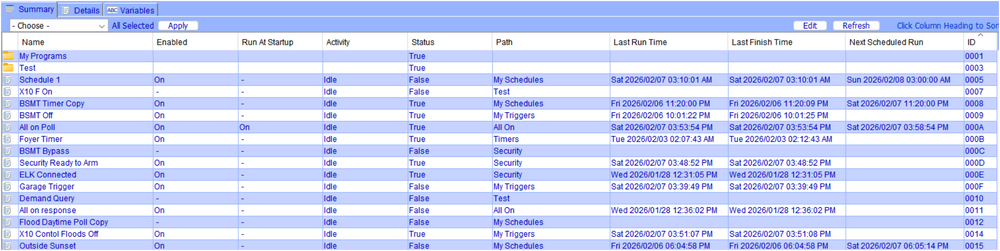
@jim_, now I need to back things up a bit: When a program is disabled, it will still show triggers in the event viewer. I find this rather frustrating. The disabled program WILL NOT execute then or else commands. Clear as mud, right? I see programs 0033 and 005D being triggered. If program 005D is disabled, the double trigger/ double scene call is coming from program 0033. As far as determining the program ID, I typically use the program summary - far right column is the program ID. I'm guessing that the "Parent" that you are referring to is the ID of the Folder the program is in.
-
@jim_ , It looks like you have a motion sensor at address 54.68.42 that is used as a control in two programs (0033 and 005D). Motion sensors send out multiple communication for each trigger event. Yours is sending out 6 separate messages. 4 of the messages the ISY has recognized as duplicates and is ignoring. Unfortunately two of the messages are being processed causing your programs to re-trigger rapidly. The result is multiple scene 21 on commands. You may want to add a lockout to your programs (to prevent re-triggering) as well as a delay to prevent the ISY from trying to send out commands while the motion sensor is hammering the PLM with 6 separate communications. Thu 02/05/2026 11:04:58 : [INST-SRX ] 02 50 54.68.42 00.00.01 CF 11 01 LTONRR (01) Motion Sensor On #1 - ISY Triggers Program Thu 02/05/2026 11:04:58 : [Std-Group ] 54.68.42-->Group=1, Max Hops=3, Hops Left=3 Thu 02/05/2026 11:04:58 : [D2D EVENT ] Event [54 68 42 1] [DON] [1] uom=0 prec=-1 Thu 02/05/2026 11:04:58 : [54 68 42 1 ] DON 1 Thu 02/05/2026 11:04:58 : [D2D-CMP 005D] CTL [54 68 42 1] [DON] op=is --> true Program 005D Control Trigger 1 Thu 02/05/2026 11:04:58 : [D2D-CMP 0033] CTL [54 68 42 1] [DON] op=is --> true Program 0033 Control Trigger 1 Thu 02/05/2026 11:04:59 : [INST-SRX ] 02 50 54.68.42 00.00.01 CF 11 01 LTONRR (01) Motion Sensor On #2 - ISY Re-triggers Program Thu 02/05/2026 11:04:59 : [Std-Group ] 54.68.42-->Group=1, Max Hops=3, Hops Left=3 Thu 02/05/2026 11:04:59 : [INST-SRX ] 02 50 54.68.42 71.1C.76 40 11 01 LTONRR (01) Motion Sensor On #3 (ISY ignores) Thu 02/05/2026 11:04:59 : [Std-Cleanup ] 54.68.42-->ISY/PLM Group=1, Max Hops=0, Hops Left=0 Thu 02/05/2026 11:04:59 : [INST-DUP 2 ] Previous message ignored. Thu 02/05/2026 11:04:59 : [INST-TX-I1 ] 02 62 00 00 21 CF 11 00 Scene 21 On Thu 02/05/2026 11:04:59 : [D2D EVENT ] Event [54 68 42 1] [DON] [1] uom=0 prec=-1 Thu 02/05/2026 11:04:59 : [54 68 42 1 ] DON 1 Thu 02/05/2026 11:04:59 : [D2D-CMP 005D] CTL [54 68 42 1] [DON] op=is --> true Program 005D Control Re-Trigger Thu 02/05/2026 11:04:59 : [D2D-CMP 0033] CTL [54 68 42 1] [DON] op=is --> true Program 0033 Control Re-Trigger Thu 02/05/2026 11:04:59 : [INST-TX-I1 ] 02 62 00 00 21 CF 11 00 Scene 21 On (repeat) Thu 02/05/2026 11:04:59 : [INST-ACK ] 02 62 00.00.21 CF 11 00 06 LTONRR (00) Modem ack scene 21 On Thu 02/05/2026 11:05:00 : [INST-ACK ] 02 62 00.00.21 CF 11 00 06 LTONRR (00) Modem ack scene 21 On (repeat) Thu 02/05/2026 11:05:00 : [INST-SRX ] 02 50 54.68.42 71.1C.76 43 11 01 LTONRR (01) Motion Sensor On #4 (ISY Ignores) Thu 02/05/2026 11:05:00 : [Std-Cleanup ] 54.68.42-->ISY/PLM Group=1, Max Hops=3, Hops Left=0 Thu 02/05/2026 11:05:00 : [INST-DUP 2 ] Previous message ignored. Thu 02/05/2026 11:05:00 : [INST-SRX ] 02 50 54.68.42 11.01.01 CB 06 00 (00) Motion Sensor On #5 (ISY Ignores) Thu 02/05/2026 11:05:01 : [Std-Group ] 54.68.42-->11.01.01, Max Hops=3, Hops Left=2 Thu 02/05/2026 11:05:01 : [INST-INFO ] Previous message ignored. Thu 02/05/2026 11:05:01 : Create REST U7 [/rest/profiles/ns/1/connection] Thu 02/05/2026 11:05:01 : Create REST U7 [/rest/profiles/ns/0/connection] Thu 02/05/2026 11:05:01 : [INST-SRX ] 02 50 54.68.42 11.01.01 CF 06 00 (00) Motion Sensor On #6 (ISY Ignores) Thu 02/05/2026 11:05:01 : [Std-Group ] 54.68.42-->11.01.01, Max Hops=3, Hops Left=3 Thu 02/05/2026 11:05:01 : [INST-INFO ] Previous message ignored.
-
From your description it sounds like you did indeed use the "Delete Modem" command. Since your current PLM was not listed as a group 0 controller, newer devices should have responded with a NAK for anything other than a simple on/off (many won't respond to an on/off either). Unless all of your devices are older (pre- 2012), I'm not sure how your system functioned. Aside from that, it sounds like the ISY now has the correct information to allow it to correctly restore your devices/scenes. It may be painful, but not nearly as painful as rebuilding all the scenes/programs.
-
Glad to hear you are narrowing in on things. One thing to note - since your devices had the "old" PLM links in their tables, they would have been trying to communicate (and timing out) on a device that was not available. Now that you have eliminated the old links, your system should be far more responsive. This is why you should ALWAYS delete devices that you are removing from the system (I.E failed). If you leave "orphaned" links in devices they will try to communicate (retries, etc) with a device that no longer exists. It can really bog down a system.
-
@jim_ , no smoking guns in your event viewer. I have a python program that parses the event viewer looking for errors. It specifically looks for INST-TX communications from the ISY to the PLM followed by INST-ACK responses from the PLM. I modeled this after a description provided by @kclenden . He was the 1st (to the best of my knowledge) to observe ISY/PLM communication errors in the Event Viewer A normal TX/ACK for a scene looks like the following (on command to group 21: 10039 Fri 02/06/2026 12:53:36 : [INST-TX-I1 ] 02 62 00 00 21 CF 11 00 10041 Fri 02/06/2026 12:53:37 : [INST-ACK ] 02 62 00 00 21 CF 11 00 06 LTONRR (00) A device direct command includes a response from the device itself. My program does not test the responses: 9629 Fri 02/06/2026 12:51:08 : [INST-TX-I1 ] 02 62 42 D7 2C 0F 11 FF 9633 Fri 02/06/2026 12:51:08 : [INST-ACK ] 02 62 42 D7 2C 0F 11 FF 06 LTONRR (FF) 9634 Fri 02/06/2026 12:51:08 : [INST-SRX ] 02 50 42 D7 2C 71 1C 76 2F 11 FF LTONRR (FF) 9635 Fri 02/06/2026 12:51:08 : [Std-Direct Ack] 42 D7 2C-->ISY/PLM Group=0, Max Hops=3, Hops Left=3 Your event viewer contained 918 total I1 communications. There were no errors (an error is where the INST-ACK <> the INST-TX). There was one "Unknown" error, and 3 timeouts (modem did not respond with a ACK). Your event viewer did not contain any I2 communications. #'s: I1ackerr: 0 I2ackerr: 0 Timeout1: 3 Timeout2: 0 Unknownerr: 1 I1Good: 918 I2Good: 0 The Unknown error came at a time when there wasn't a lot going on. No good explanation for the error. The ISY was attempting to turn on group 21. The line labeled with a "U" should have been an INST-ACK 02 62. This command did not go through. Not sure whether the ISY retried the command. There is another ON command processed 13 seconds later. 2419 Thu 02/05/2026 14:17:45 : [INST-TX-I1 ] 02 62 00 00 21 CF 11 00 U 2420 Thu 02/05/2026 14:17:45 : [UNKNOWN ] 02 00 The timeout errors also came at time where there wasn't a lot going on. The INST-TX command below should have been ACKnowledged within seconds (INST-ACK 02 62 00 00 1F CF 13 00 06). No communications were received by the ISY in 1:10 after the command. 8449 Fri 02/06/2026 12:25:39 : [INST-TX-I1 ] 02 62 00 00 1F CF 13 00 T1 8450 Fri 02/06/2026 12:26:50 : [INST-SRX ] 02 50 54 68 42 00 00 01 CF 11 01 LTONRR (01) I did see some areas where there was very high activity. In the section below 3 devices and 6 scenes are turned off in rapid succession. I've never seen that many INST-TX commands "stacked" without a response from the PLM. The PLM did eventually ACK all of these, I am truly surprised. This is most likely a program executing an OFF to multiple members (it could be an external REST command). You may want to look at adding some delays to prevent overloading the PLM. 4898 Fri 02/06/2026 07:16:55 : [INST-TX-I1 ] 02 62 58 CA 24 0F 13 00 4899 Fri 02/06/2026 07:16:55 : [INST-TX-I1 ] 02 62 33 7A 65 0F 13 00 4900 Fri 02/06/2026 07:16:55 : [INST-TX-I1 ] 02 62 4E B1 E0 0F 13 00 4901 Fri 02/06/2026 07:16:55 : [INST-TX-I1 ] 02 62 00 00 1B CF 13 00 4902 Fri 02/06/2026 07:16:55 : [INST-TX-I1 ] 02 62 00 00 14 CF 13 00 4903 Fri 02/06/2026 07:16:55 : [INST-TX-I1 ] 02 62 00 00 12 CF 13 00 4904 Fri 02/06/2026 07:16:55 : [INST-TX-I1 ] 02 62 00 00 1C CF 13 00 4905 Fri 02/06/2026 07:16:55 : [INST-TX-I1 ] 02 62 00 00 16 CF 13 00 4906 Fri 02/06/2026 07:16:55 : [INST-TX-I1 ] 02 62 00 00 1E CF 13 00 4907 Fri 02/06/2026 07:16:55 : [ZW-TX-A 01253 2 0 ] [ZY002_1] Binary Switch Set val=0 duration=255 You have some scenes where the command is repeated. The below shows an ON command to group 11 being sent twice. Multiple commands to a scene can improve it's reliability but there should be some delay between the commands. 3807 Thu 02/05/2026 17:21:25 : [INST-TX-I1 ] 02 62 00 00 1F CF 11 00 3808 Thu 02/05/2026 17:21:25 : [INST-TX-I1 ] 02 62 00 00 1F CF 11 00 3809 Thu 02/05/2026 17:21:25 : [INST-ACK ] 02 62 00 00 1F CF 11 00 06 LTONRR (00) In summary, this is mostly good news. You have good communication in general (Hops left = 3 in most cases) and 0 communication errors. If you happen to capture an "all-on" event in the viewer, I would be happy to look at it. Aside from that, I would suggest inspecting your programs from proper delays, particularly where motion sensors are being used. You can always post your programs as well. Many forum members with far more programming experience than myself. EDIT: I should have asked earlier - can you provide the addresses of the devices that are turning on? If many devices, you can provide a few.
-
@jim_ , no worries. We'll have a look and see whether errors are occurring. There's no "easy" doc to explain the communication protocol shown in the event viewer. What you are seeing is the Host to Modem communication + a lot of ISY notations and program diagnostics. If you are using PG3 (or whatever it's call these days), things get even more confusing. For understand the raw Host to Modem protocol, my favorite doc is the following: https://madreporite.com/insteon/Insteon2412s_modem_dev_guide.pdf There are newer docs (written for the HUB) but the above does a nice job of explaining the protocol without adding too much fat. Many thanks to the Madreprite site for continuing to make this information available. There is other good Insteon information on the site as well.
-
Possible that you didn't power cycle your ISY after replacing the PLM. The ISY reads the PLM address on powerup/reset. If you replaced the PLM and ran a restore modem (PLM) without the powercycle, the ISY would still have the OLD PLM address - it wrote OLD information to your devices. The Delete Modem command is normally used to remove the PLM address from all of your Insteon devices. Since your current PLM address is not in the device(s) link table(s), I'm not at all sure what the command would do. Instead, proceed as you would if replacing the modem normall: Backup your ISY - just because... Power cycle the ISY to make sure is has your current PLM address (or verify using the show plm info tool). Perform the "Restore Modem (PLM)" function. The ISY will write changes to your PLM and all of your attached Devices. Your link tables should update with the current PLM address. Remember to put your battery devices into linking mode. Assuming things work and you verify that your current PLM address is written to the devices - backup your ISY again. Give it a novel name to indicate this backup has the NEW PLM.
-
@jim_ , a log that spans the actual event would be optimal. Since that may be difficult, a log spanning say 24 hours would help us to understand if there are errors occurring regularly (not all errors produce events).
-
The All-On is a valid Insteon command. When a communication collision at the PLM occurs, a valid outgoing scene command is corrupted into an "All-ON or All-Off" scene command. All older Linked Units will respond In recent years, Smartlabs began removing the "All-On/All-Off" command from individual devices. Many dimmers/relays with firmware newer than V.45 have had the command removed and will Not respond. One of the links I provided describes how to test for this. While it's possible to have a data collision at the KPL, it shouldn't produce an "all-on". The reason are rather dry and technical. It is completely possible for the KPL to cause a collision at the PLM. This typically occurs when the KPL is a scene controller and also triggers a program. MS's are high on the list of instigators because they have the annoying of sending multiple communications to the PLM (increasing the likelihood of a collision). To your last question on messaging - is this is a true "all-on" event you will not see evidence in the event viewer. You may be able to isolate the trigger event through the process of elimination (as you are doing), the the event will look like a normal trigger. Having said the above, one of our forum members has noted communication errors between the PLM and EISY ( @kclenden ). Would you mind posting a level 3 event viewer capture? We could go through the PLM/ISY communications to see if errors exist.
-
The "Random" event is caused by a communication collision at the PLM. The result of the collision is an Insteon "All-On" command sent to all devices. Devices that have not had the command removed will be affected.
-
If the ISY has no knowledge of the event, and the Event Viewer isn't showing anything, this would appear to qualify as an "all on"event. Motion sensors and KPL's calling programs that in turn call scenes involving the triggering device are known instigators. The Wiki Guidance is below. There are also numerous posts on the forum. Smartlabs has removed the all-on command from some recently produced devices (V.45). Your IOLinc is probably susceptible. The second link below shows how to test for susceptibility. The 3rd link shows devices that have been tested for susceptibility and have passed. As a precaution, you should probably perform a "restore device" on your problem units to make sure no extraneous links have crept in over time. Wiki link on preventing all on events https://wiki.universal-devices.com/INSTEON_Random_All_On_Events You can test for susceptible all on devices as shown here:
-
I decided to give this a run on my used/refurb Mini-PC (HP Elitedesk 800) with Win11 Pro and 32G ram/ 1T SDD. My 1st run using IOX, and no Java customizations. We are at 4 days running at the moment with the event viewer open. The MiniPC does have a hardwired LAN connection, but otherwise is a rather minimalist system and extremely inexpensive. It runs most of my automation well including Home Assistant, Houselinc, and (now) IOX. As @Geddy indicated, hardwired LAN is greatly preferred. Beyond that, I saw that you were using MacOS in another thread - I have no experience.
-
I'm not aware of any timeout on the Admin Console (or forgot). I simply let it run
-
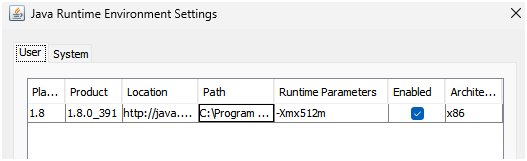
I've been able to leave the event viewer running on my laptop for that long. Longest file I appear to have is 8 days ~122K lines. I've obviously turned off sleep and hibernate (win11). Not sure if it matters, but I increase the java memory allocation to 512M (-Xmx512m parameter). https://wiki.universal-devices.com/index.php?title=Main_Page#Admin_Console_is_very_slow_or_hangs