
IndyMike
Members
-
Joined
-
Last visited
Everything posted by IndyMike
-
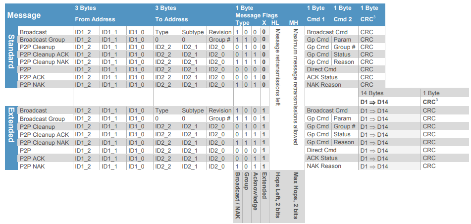
@kclenden , we have confirmation of the invalid sequence 1) 02 62 00 11 00 CF 13 00 was acknowledged by the PLM and turned all lights off (responders to group 00). 2) 02 62 00 11 00 CF 11 00 was acknowledged and turned all linked group 00 lights ON. 3) 02 62 0F 19 00 CF11 00 also acknowledge and turned all linked group 00 lights ON. I used a spare PLM that had been factory reset. I used Houselinc to link 3 devices to the PLM (group 00). All three devices were older and had been previously identified as responders to the Insteon All-on command. The PLM was an older 2413UH version V1.5 Date Code 1123. As far as the invalid format is concerned, the "Broadcast Group" command (message flag CF in the above) only considers the lower byte of the address since groups are limited to 00 to 255 (00 to FF). Group 00 is normally reserved for devices linked to the PLM. Group FF is defined as "all linked devices". I am not entirely sure how they differ. I normally use group FF for my testing. Wasn't entirely sure whether group 00 would work. I was also not sure whether the extraneous data in the upper address bytes would be rejected by the PLM. They were not. I had never considered that the PLM might miss or swap entire bytes in my testing. Your data has been an eye opener. The following is from page is from the "Insteon Whitepaper: The Details" version 2 - 2013 (page 21). I know you understand this information well. I am not trying to be insulting or pedantic. I am hoping that others may have the same Ah-Ha moment that I had when I saw your log. We are now well off the track of the OP's original thread. This may be related to what @someguy is experiencing. I do not believe it is related to @jlloyd_UD 's issue which appears to be purely Alexa base. WE should either start a new thread or ask for his blessing to continue.
-
@kclenden , thank you again for the information. I am currently writing a Python script to parse through the even viewer data. The differences between your EISY data and my ISY994 are significant. I have many instances where the ISY will issue multiple commands prior to receiving an ACK from the PLM. I am trying to implement logic to "look ahead" for proper ACK's. It's not easy (and I'm a python novice). My ISY instance hung today after roughly 50 hours. I have not seen a PLM ECHO error as yet. I will move the routine to another dedicated PC that will hopefully be able to run longer. I appreciate the offer of providing your program. Please allow me some time to poke at this from my side. I see advantages in having multiple eyes/approaches to addressing the problem. I should be able to test the invalid message sequence (02 62 00.11.00 CF 13 00) in the AM. I see no reason that this would not produce an ALL-OFF. I use the old Busyrat PLM tool to write command sequences to the PLM. I retired the old windows PC that had the tool installed. Resurrected the PC from dead storage a little while ago and verified the tool functionality. Will try executing the all off in the early AM so as not to upset family members (and the Boss).
-
@kclenden , extremely interesting log. Thank you for posting. Very nice presentation with the line numbers to correlate things. I don't want to take this thread sideways, so I'll try to be brief. Observations: 1) I have never seen mismatches like this using my ISY994. You are, however, looking far harder than I have. I have been running the event viewer since your 1st post in an attempt to find mismatches. 2) I have never experienced the "LINK INFO" message using the ISY994. This may be a EISY only message. You seem to be highlighting these occurrences. Curious if you believe it's related. 3) I do see where the PLM incorrectly acknowledged a Group Broadcast OFF command to Group 00 (line76627). If you actually witnessed an All-Off that's kind of a smoking gun. I am not sure if this is the infamous All-on/All-off from the past, or something new.
-
Wow - that is exactly what I've been theorizing was occurring at the PLM serial interface. It didn't seem logical that a powerline collision could reproduce the proper bit coding/timing/and checksums. A collision at the serial interface has far fewer checks and balances. Alas, I have never actually seen this in the event viewer (don't have a EISY). I would love to see any examples of echo back errors that you may have. I have not had any All-on events for some time, but I have been adding delays and eliminating Insteon Motion sensors tying to make the system more reliable. I would be willing to take things in the opposite direction to actively try to break the system in order to troubleshoot.
-
My kneejerk reaction is that this is (again) alexa commanding your devices on using the rest interface. The event viewer posts that you have made showed a rest command instructing the EISY to turn on the device @48.15.F2. That's a very specific device direct command. If this is still occurring, you should be able to view with the event viewer and the EISY log. I am not Alexa knowledgeable. It's possible that when you upgraded your BB Fan device you also eliminated the link in Alexa. I do use the rest interface extensively between my ISY994 and Home Assistant. I have not seen problems with miscommunication and am not sure what that would look like. My last comment relates to the age of your Insteon devices. The are older Icon powerline only devices (I still have several). I did get tripped up a while ago by a light that began responding to an X10 command (2876S V.28 Device). I still have some X10 floods that activate and announce motion. My driveway flood began turning the icon device on/off. The ISY994 was completely blind to this. A factory reset/restore eliminated the X10 address in the switch. The ISY does not (to my knowledge) give us a way to check whether devices have X10 addresses programmed. It's kind of a blind spot and the reason that I bring it up. For years protocol dictated that you factory reset every device out of the box to prevent X10 addresses that might exist from factory programming. Having said the above, it would be extremely unlikely that you happen to have 4 icon devices with X10 addresses programmed. If you suspect this is the case, let us know. They are ways of testing using x10 all-on house codes.
-
Hey Someguy, The 48.15.F2 device is absolutely being turned on by a Rest command. An external device is instructing your EISY to turn on the device. Where the command originated from I can't tell you. @kclenden posted a method above on how to interrogate the Error log file to find the IP address of the sender. Aside from that, all of the commands that I've seen posted are device direct commands. In other words the commands are targeting specific device addresses (no scenes). I am not a Alexa user. I am not sure whether that information helps.
-
Correct - this was intended as a stopgap/troubleshooting step until you resolved the root cause. It allows programs and schedules to run on the EISY while preventing Rest commands. I would not call the RJ45 network connection fragile, but agree you would not want to disconnect/re-connect as a long term solution. If you are concerned about this, most routers allow you to "pause" a network connection to specific devices. Either way, it's far better than continuously performing power cycles on the EISY.
-
@someguy, please do post any event viewer info that appears pertinent. Unfortunately, I am not knowledgeable on the Alexa control/integration. I am simply reading the event viewer logs and interpreting what the EISY is receiving. @Geddy had earlier posted a link pertaining to the Amazon Integration.
-
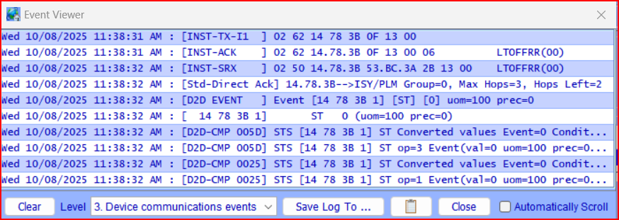
@jlloyd_UD, Resetting your switches will not help. Base on your event viewer, they are responding to valid communications from the PLM/EISY. The EISY is, in turn, responding to a valid REST command instructing it to turn ON/OFF an Insteon device. Your latest Event Log doesn't offer any new insight (at least for me). You have 3 REST "profile" commands that I can't identify. At 11:07:00 AM the EISY receives a valid Rest command to turn OFF device 40.16.5C (highlighted RED) The Violet Entries are the ISY/PLM/Device communicating the OFF command sequence. The green entry is the ISY summarizing the OFF command communication. Good news is that you have very good communication to this device. When I suggested disconnecting the EISY, I was proposing disconnecting it from your network (RJ45 network connector) not the PLM. This was intended to be easier then powering down the EISY completely. It would allow your programs and other EISY events to run while eliminating Rest commands. un 10/12/2025 11:00:42 AM : Create REST U7 [/rest/profiles/ns/0/connection] Sun 10/12/2025 11:05:32 AM : Create REST U7 [/rest/profiles/ns/0/connection] Sun 10/12/2025 11:05:44 AM : Create REST U7 [/rest/profiles/ns/0/connection] Sun 10/12/2025 11:07:00 AM : Create REST U7 [/rest/nodes/40%2016%205C%201/cmd/DOF] Sun 10/12/2025 11:07:00 AM : U7 Rest: submitCmd([40 16 5C 1],[DOF],[<NULL>]) Sun 10/12/2025 11:07:00 AM : [INST-TX-I1 ] 02 62 40 16 5C 0F 13 00 Sun 10/12/2025 11:07:00 AM : [INST-ACK ] 02 62 40.16.5C 0F 13 00 06 LTOFFRR(00) Sun 10/12/2025 11:07:00 AM : [INST-SRX ] 02 50 40.16.5C 48.EC.F5 2F 13 00 LTOFFRR(00) Sun 10/12/2025 11:07:00 AM : [Std-Direct Ack] 40.16.5C-->ISY/PLM Group=0, Max Hops=3, Hops Left=3
-
Your earlier "Event Viewer" post showed that the EISY was receiving REST commands instructing it to turn on/off device 60.41.6B. That is the EISY simply responding to an external command. Not a fault of the EISY or the PLM. It's a valid command that is being received through the network interface. I don't use Alexa or PG3 so I am not much help in troubleshooting. I suppose you could try eliminating specific device links (60.41.6b) from Alexa to see if that corrects the behavior for that specific device. You can also disconnect the EISY from your network during the night (rather than unplugging it). Without a network connection, the Rest interface should not be operative.
-
That appears to be rather damning. Not sure what device 60.41.6b.1 is, but it is absolutely being turned on by a rest command (Alexa?). I had seen other posts from users of the Eisy that showed "Rest" commands in the event viewer and was hoping yours would show the same. My ISY994 does NOT indicate Rest commands. Not a solution, but now you know where the command is originating from. Hopefully you can drive to a solution with the help from others on the forum. [comment: the following are the steps that initiated a random turn on of a light thru I3 switch 60.41.6B.1 ] Wed 10/08/2025 03:56:57 PM : U7 Rest: submitCmd([60 41 6B 1],[DOF],[<NULL>]) Wed 10/08/2025 04:04:15 PM : U7 Rest: submitCmd([60 41 6B 1],[DON],[<NULL>]) Wed 10/08/2025 04:04:24 PM : [60 41 6B 1 ] ST 255 (uom=100 prec=0) [comment: I initiated a "shut off light" command using Alexa plus spoken] Wed 10/08/2025 04:05:07 PM : U7 Rest: submitCmd([60 41 6B 1],[DOF],[<NULL>]) Wed 10/08/2025 04:05:07 PM : U7 Rest: submitCmd([60 41 6B 1],[DOF],[<NULL>]) Wed 10/08/2025 04:05:07 PM : [60 41 6B 1 ] ST 0 (uom=100 prec=0)
-
You seem to have established that unplugging either the PLM or (more importantly) the EISY eliminates the random on problem. In my mind that eliminates noise, absorption, corrupted link tables and a host of other items. Re-winding to your very 1st post, you had mentioned the Alexa plug in. This and other plug-ins (Elk) are absolutely capable of activating various devices through the EISY/PLM. Can you try capturing a "Event Viewer" transmission when one of the random lights activates? You'll need to have the viewer on Level 3 to see the transmission. I understand that this may be difficult because of the randomness of the events. The following is an event where my Home Assistant install instructs the ISY to turn off a basement light (using the Rest interface). It's indistinguishable from a normal ISY command (I'm using a ISY994). I'm hoping you have something similar going on - not noise, bad links, or a failing PLM. If you can't seem to capture one of the events, you could try disabling your various plug-ins. I really don't use them on my ISY994, so others will have to assist here.
-
-
Got it. Hope you're able to find someone to write a Plug-in.
-
Assuming that your screen and window frame are aluminum, your should be able to make the magnetic reed switch work over a 1/2" distance. You may need to tune the magnet (increase strength, stack, etc) to get things to trigger reliably. There is nothing magic about the magnets included in the sensor kits. You can replace with stronger versions and stack them to increase flux strength/close distances. Neodymium Magnet The Insteon sensor is easy since you have the ISY, but the battery life isn't the greatest. That could be an issue with skylights. The Yolink has good range and battery life, but you'll need a hub and a plugin. The garage door tilt sensor is elegant, but you probably don't have enough range of motion on your skylights. I use Zooz tilt sensors on my garage doors and they work well. They are not tunable (most are not) and require ~ 60 degrees of motion to trigger reliably. I have played with some Tuya Zigbee tilt sensors (ZG-103Z) that report X,Y, and Z axes tilt angles. These would require a Zigbee interface/mesh and probably are not supported by the EISY (requires Home Assistant). Not sure if there are other devices available that report actual angles rather than just Open/closed.
-
@smorgasboard, thanks for posting back with your findings. Sounds like you have found a path for controlling some of your skylights. My understanding is that Velux/Somfy use a closed RF protocol to interface their skylights/shades. The KLF-200 can speak this protocol and connect to MANY (200?) motors. You are correct that the KLF-200 is limited in the number of switch INPUTs that can be used to control the skylights. The value of the KLF interface is it's ability to communicate with other controllers (HA/EISY) that can operate the skylight(s) through it's API. That's my understanding anyway. If it's incorrect, please post back. https://community.home-assistant.io/t/velux-klf-200-pairing-with-somfy-io-motors-and-remotes/248075/14
-
No experience with Velux or the interfaces. However, a post on the HA forum indicates that the KLF 200 can handle far more than 5 devices. I'd say clarification from the manufacturer would be in order: VELUX America LLC 1-800-88-VELUX https://community.home-assistant.io/t/how-to-control-io-homecontrol-velux-devices-blinds-somfy/88917/3 Please do post back with anything you learn. Others will have the same questions.
-
Sorry, I'm not going to try to re-quote 10+ years of history. Search the forum's
-
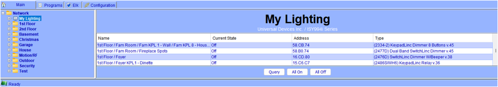
To the best of my knowledge, Smartlabs HAS NOT removed the all-on command from current PLM's. They are still capable of sending the command (it is a valid command). Smartlabs HAS removed the all-on command from some of the newer Insteon modules. To the best of my knowledge, the IOLinc is STILL SUSCEPTIBLE to the all-on command. The ISY can still send an all-on command if you wish to test your devices. Navigate to the "My Lighting" item in the Admin Console Tree and you will see the all on at the bottom of the window. This will execute the group all on command. Devices that do not respond have been "fixed" or can't hear the communication. Devices that do respond are susceptible. Most of the issues with all on events seem to involve motion sensors, keypads, or devices that trigger programs that talk beck to the same device. I'm not aware of any specific Alexa issues (but then i don't use Alexa). The wiki mitigation posted above works reasonably well. There are Many posts on the forum. Try searching "site:"forum.universal-devices.com" all-on event" Best of luck.
-
Any error lights on the 994? You may want to remove and check your Sdcard (plug it into a windows machine and check for errors). If you find errors, I would highly recommend replacing the card. You can try a "repair" via windows, but I'd consider that a stopgap. Procedure for replacement is in appendix 😄 of the ISY994 users guide: https://docs.universal-devices.com/production/ISY User Guide 4.2.8.pdf
-
Sorry, thought you were still using the ISY994. I don't know what format the SSD uses. There are posts on how to re-flash the SSD: https://forum.universal-devices.com/topic/42174-polisy-ssd-image-restore-process-for-a-corrupt-ssd/. I also don't know if the EISY can read the information on the SSD. I would try a mSata to USB adapter and a PC first to see if it registers.
-
@apostolakisl, that's rough. Sorry to hear. My only comment(s) would be - check the power supply to see if it fried, and check the SDcard for corruption. Two easy ways to recover your configuration.
-
You can view the programs in a backup. Identifying a specific program and restoring it is rather painful. Copy one of your backups to a separate directory in case things go bad. The 1st screenshot below is the result of an UnZip of one of my backups. Use 7Zip or something similar to open your backup .Zip. Windows explorer will NOT work. You will see the file "uuid.xx.xx.xx.xx.xx.xx.zip". Unzip this to your directory. Open the "uuid.xx.xx.xx.xx.xx.xx.zip" file in 7Zip as well. Extract the CONF folder. Within the CONF folder you will find a D2D folder. This contains your program files. The "*.PGM" files are in XML format. Your challenge will be to identify which file you want to restore (not easy). You can export your current programs to try to determine the program numbering (ID) and what is missing. Beware that Exporting the entire "My Programs Folder" produces an XML file that can't be interrogated by any XML viewer that I have found (format error). I have been successful in exporting individual program folders (non-nested). I'm quite sure this is not the answer you were hoping for. Unfortunately, it's all I can offer. Directory showing Backup Zip, UUID Zip, and CONF file folder CONF Folder contents: D2D Folder Containing Program Files 000A.PGM Contents


-
As indicated above, the Zen32 does not send ON/OFF commands. Instead it sends "keypressed" events. The ISY appears to be interpreting the "keypressed" event as an "ON" event. Said differently, the ZEN32 will not send an OFF as interpreted by the ISY. You can still use programs and variable to interpret the successive "ON" events: {on program} if 'ZEND32 Button 2' is switched on and $ivar = 0 {0 = off} then {turn devices on} set $ivar = 1 {1 = on} {Off program} if 'ZEND32 Button 2' is switched on and $ivar = 1 {1 = on} then {turn devices off} set $ivar = 0 {0 = off}
-
@Techowl, I'm in agreement with @Brian H. It sounds like you have a device that is radiating signal @310 MHz and is effectively jamming your transceivers. If it is a device that is failing (oscillating) it will not be transmitting the proper X10 format and will be ignored by the transceivers - you won't see any events. You have a couple of tools at your disposal - 1) The tried and true circuit breaker approach. Turn off circuits until the noise stops (communication improves), then isolate devices on the circuit. 2) Use your transceiver to determine where the noise source isn't. Move the transceiver around the house to find an area where the remote range improves. Then reverse the process to find where the range is worst (noise source nearby). It is of course possible that the noise source is outside your home. The breaker test would confirm that.


