
IndyMike
Members
-
Joined
-
Last visited
Everything posted by IndyMike
-
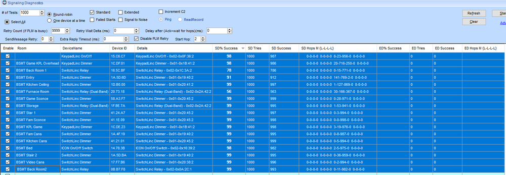
@brockp , it appears that Houselinc is still available here: https://support.insteon.com/support-knowledgebase/2016/6/1/houselinc-windows HouseLinc is a PC based interface for Insteon control. It was the forerunner of Smartlabs Hub based system. I still use Houselinc for it's diagnostic/signaling capabilities. I have it setup on a Windows 11 mini PC with a USB to serial adapter to the PLM. The following was a test that I ran after having issues to a new refrigerator install. Houselinc ran 1000 tests on 17 different devices and rolled up the success %. I had "Disable PLM Retry" selected and "Hops" set to 2, so this was similar to a standard ISY scene (no retries, HOPS=3). You could certainly use this to give your questionable PLM's a workout. 1 word of caution - using Houselinc to link to existing devices will alter their link tables (without the ISY's knowledge). Make sure to use the ISY to restore the Link tables after testing.
-
@someguy , now that I've re-read the post, you are probably correct about "Instagram" being a typo. You might be surprised to learn that there is an Instagram add-on for Home Assistant... There's a lot of conflicting information here. You're symptoms are following the "random on" events that have been attributed to communication collisions or PLM to EISY serial errors (pointed out by @kclenden ). The Event log that you provided earlier did NOT show any PLM to EISY serial errors that I could find. @kclenden is far more experienced at screening for these. I would welcome his input on the issue. Questions and things to try: Your newer devices should not be susceptible to an all-on command from the PLM. Please verify that this is true by executing an ALL-ON from the MY Lighting Admin console and then physically which devices turn on. Devices like the IOLinc were not updated the last I checked. When you find a light on unexpectedly, does the ISY have knowledge of the Light State? If it does it could point to a Rest command telling the ISY to turn devices on (the ISY knows it sent an on command in response to a Rest request). Try disconnecting the ISY from the Lan to interrupt Rest communication. You'll likely need to leave the system disconnected over a couple of nights to verify any improvement. Manually linked devices can activate devices outside of the ISY's knowledge. I've had this happen previously when visitors were in the house and accidently put devices into linking mode. Scan the device link tables and restore if necessary. The link table that you provided earlier showed only a link for your PLM. Only your PLM (or another controller) should be able to activate this device. If nothing above has helped eliminate the problem - disconnect your PLM. That should prevent any device direct communication. Check for "other" controllers. In the past I've had HouseLinc running on a separate PLM. A PLM can control your devices even with NO links in the device table (just verified this AM). Make sure you don't have any other controllers capable of issuing device direct commands to Group 0. If things are still acting up, we are down to X10 communication or local power upsets. You've already factory reset some of your devices - that should eliminate any programmed X10 addresses. If you factory reset a device and leave the link table blank (do not restore) the only device that should be able to activate it would be a PLM using a device direct command. An all-on command should NOT turn the device on. If the PLM is disconnected, there shouldn't be any controllers capable of turning the device on. If it does, there's something very next level going on. Please report back your findings for the all-on test.
-
@someguy , from what I remember, you did not have any Alexa communication in the event viewer file that you provided. You also had only 1 link in your affected device link table (to the PLM). That really doesn't leave many options. Since you do have a PLM link in the device, the PLM (EISY) can still turn on the device. That includes any REST device (alexa and other). You might try disabling (unplugging) your network connection to eliminate external commands. @oberkc mentioned that he has been having issues with Instagram communications - I have no experience with that but it sounds like it could be a player. The other possibility would be an "all-on" event. Your older devices are susceptible. The newer device (71.C2.58) should not be. Not sure what this device is - please post back and confirm. You can test to determine whether your devices respond to the "all-on" command from the admin console. From the "my lighting" tab in the admin console tree, hit the "all-on" button. After activating you'll need to visually inspect for devices that have responded. Newer devices will not respond (command removed). Older devices will respond. Very curious about your 71.C2.58 device.
-
@BobM99 , to the best of my knowledge you will not receive a "message" from querying X10 devices. There are not many 2-way x10 devices out there. Most devices will not respond to queries. Even if a X10 module is 2-way compatible, the ISY will not generate an error if it does not respond to a query (ISY994 won't generate an error). If you are seeing a "Request Failed" error from the EISY, it's possible that it is not communicating to the PLM. Check the "Tools\Diagnostics\PLM Status" for connection errors. If the PLM is a recent replacement, it's possible that it does not support X10. I've heard that X10 was removed in some newer modules, not sure about the PLM's themselves.
-
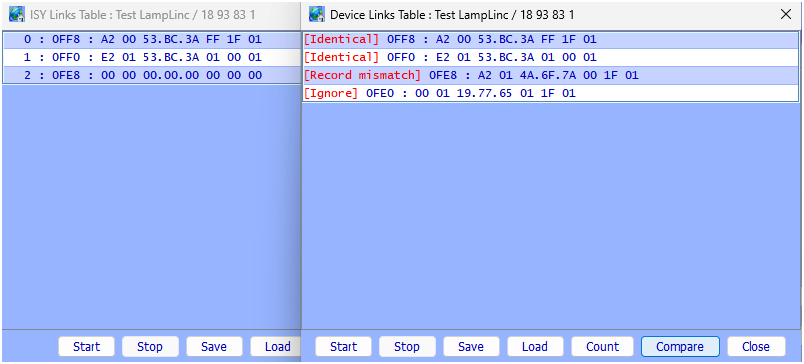
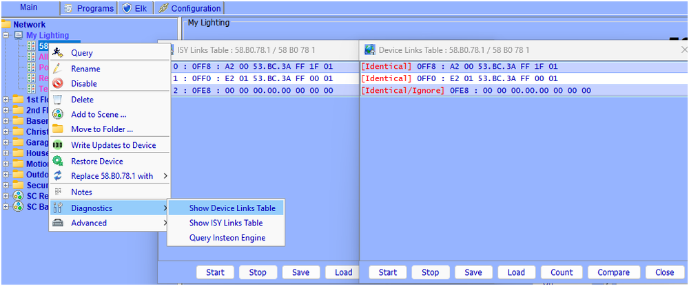
@PapaBear , the fact that this is a new sensor is relevant. It's possible that it's mislabeled or just defective. One curious item is the device address - 45.D1.A2. I have 4 of the MSII's that are already several years old. They all start with the address 4A.xx.xx. Insteon device addresses don't normally decrease on newer units. One last thing to try before we declare the unit "broken" - manual link to another Insteon device. This is just in case you have a misprinted address label on the MSII. I just did this with a LampLinc I had laying around - Place your MSII into link mode by holding the set button for xx seconds Place the device you with to link into link mode. Linking should be almost immediate. Assuming this works, you can find the MSII address in the link table of the device you just linked (use show device links + compare). In the example below the mismatched link is the manual link just added. The 4A.6F.7A is the address of my MSII. Remember to restore your test device to eliminate the manual link.
-
@jlloyd_UD , please report back your progress. I have to believe there are others similarly affected.
-
@jlloyd_UD , the last I remember you were able to stop the random on/off activity by unplugging the EISY from the Lan. In my mind that places to problem external to the EISY. Filters, resets, and restores of devices likely will not help. My suggestion at this point would be to: Nuke the Alexa/Portal integration Verify (over days) that the problem has been resolved. Add devices back to the Alexa integration SLOWLY. Unfortunately, I do not know how to accomplish the above nor do I know how much work is involved. Hopefully the forum can help here. If not, I would suggest opening a ticket with UD. While not specifically an EISY problem, I'm sure they could assist in eliminating the integration.
-
@oberkc , You are correct that it doesn't hurt to try... I just ran both methods and they work equally well with my spare MSII's. That said, I am using an ISY994 whereas @PapaBear is running the EIsy. @GlowingHair , I believe you are referring to hitting the "Node limit" in the standard ISY994 (254 nodes). PapaBear is running the EIsy. I don't know the node limit but believe it to be substantially higher than the ISY994. I don't recall anyone hitting the Eisy limit as yet.
-
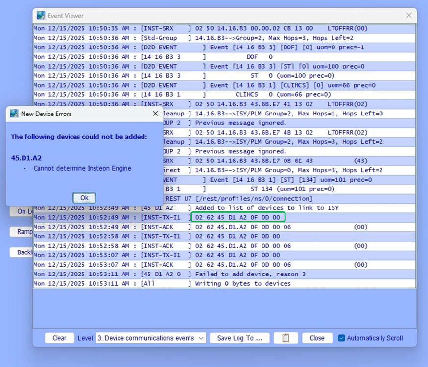
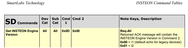
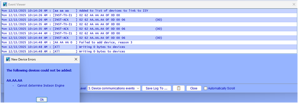
@oberkc , simply two different methods to link. Bottom line is the command shown below that is being executed by the ISY is correct (get Insteon Engine Version). If the MSII hears to command it should respond with an I2 engine version. It is not responding which leaves us with the following options: Device address is incorrect. Possible, although I've never encountered a mis-printed label. There are methods where the device can be manually linked to determine it's address. The device can't hear the PLM because of interference in the area (or PLM can't hear the MSII). Move to a different location and re-try. Faulty MSII (it happens)
-
@PapaBear , the ISY is trying to contact the MSII. It retries 3x and then times out. Did you happen to try monitoring the Event Viewer while re-connecting power to the MSII? I'm assuming you had the sensor connected previously. You also seem to be getting a lot of activity from the device @14.16.B3. I'm guessing it's a thermostat. That's both good and bad. The thermostat is communicating well with the Insteon network (do know the point of access). The bad may be the traffic it's throwing at the system. You might still try re-locating to a separate room - this will force a different RF access point to the system.
-
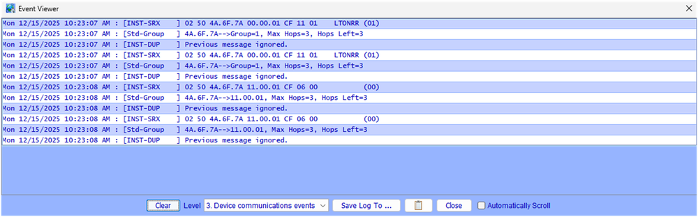
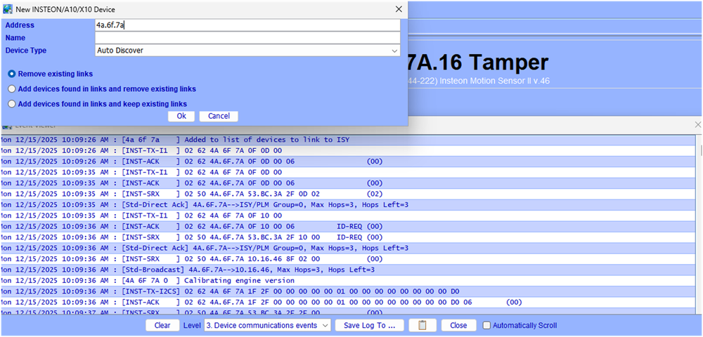
@PapaBear , I've been taking some swings at this and have not been able to reproduce what you are seeing. I've tried different communication modes (I1 vs I2), linking methods, power methods, and device versions. Things seem to just work. Would you mind posting the contents of your Event Viewer when things fail? The following is what I get when I intentionally enter in the device address. The ISY tries 3x to communicate with the device and then times out with the error message. Another possible check - If your MSII has been linked to the PLM previously, it will still contain the PLM address (even after a factory reset). Assuming the PLM still contains your MSII link (hasn't been restored from backup), you will see the MSII address pop up in the event viewer when you apply power. The communication below is from my MSII @4A.6F.7A telling the PLM that it has turned on when power is applied. Use this to quadruple check your device address (labels do get old and disfigured). The following is the method that I've settled on for linking the MSII's. Using "Auto Discover" is easier that scrolling to the bottom of the device list, and it populates the Sensor Version (v.46 below). If none of this appears to work, it is possible you simply have a defective MSII or RF Interference in the area around your PLM. You could try linking the sensor away from the PLM but close to a different RF repeater. The MSII's are 915 MHz and it's possible that you would have other devices in this range. That's not a problem that I've encountered. It is also possible that you have device(s) spamming the powerline and disrupting things while you're trying to add the device. The event monitor should show evidence if this it the case.
-
If your program turns of/off a single device, it will request a response from the device. If your program executes a scene, no cleanups are performed. Example program with a Scene ON + a device On. The event viewer output shows that the scene does not request a response from the device. Turning the device itself on will request a response. Test - [ID 0071][Parent 0003][Not Enabled] If - No Conditions - (To add one, press 'Schedule' or 'Condition') Then Set 'SC Basement Bed' On Wait 2 seconds Set 'Basement / Basement Bed' On Else - No Actions - (To add one, press 'Action') EVENT VIEWER OUTPUT ###### following is the program turning on a ascene for my basement light - no verification is performed ### Thu 12/11/2025 08:43:42 PM : [ Time] 20:43:48 7(0) Thu 12/11/2025 08:43:42 PM : [INST-TX-I1 ] 02 62 00 00 59 CF 11 00 Thu 12/11/2025 08:43:42 PM : [INST-ACK ] 02 62 00.00.59 CF 11 00 06 LTONRR (00) ###### program turning on the individual light - Light responds with 2 Hops left ######### Thu 12/11/2025 08:43:44 PM : [INST-TX-I1 ] 02 62 13 0A 51 0F 11 FF Thu 12/11/2025 08:43:44 PM : [INST-ACK ] 02 62 13.0A.51 0F 11 FF 06 LTONRR (FF) Thu 12/11/2025 08:43:44 PM : [INST-SRX ] 02 50 13.0A.51 53.BC.3A 2B 11 FF LTONRR (FF) Thu 12/11/2025 08:43:44 PM : [Std-Direct Ack] 13.0A.51-->ISY/PLM Group=0, Max Hops=3, Hops Left=2 Since your scene sounds like it is intermittent, I don't believe you have a link problem. If there were bad links, the devices would never respond. If you wish to look for bad or missing links,: Right click on a device in the admin console tree. Select "diagnostics/show device links table" Once the link table has finished populating, click the "compare" tab at the bottom of the table. A second table will open showing what the ISY believes the table should contain. Any errors will be noted in the original table. ###### Note - If you see an error flagged with a data value of ": EA" this is not an actual error. #####Devices that show errors can be corrected by right clicking the device and using the "restore device" For assessing communication issues - You can query your devices with the Event Viewer open and set to level 3. Inspect the "Hops remaining" response from the device. Normally commands are sent with max Hops = 3. Responses received back with 3 hops remaining is excellent, 0 not so much. You can also perform a scene test from the "Tools Menu". This will turn a scene on and then back off. It will request cleanups from the devices and indicate whether they responded properly. This is actually a rather rigorous test.


-
@dennisric , the "flashing" sounds like a noise and/or power supply filtering problem (capacitor dying). Are your togglelincs on the same circuit? Have you changed the loads on the switches? Any recent issues with the utility transformer/neutral line to the house? (or other electrical work). I agree that a simple reset/restore is easy and prudent. If that doesn't work you might try swapping one device out to see if that corrects the problem. The togglelincs are ~10 years old or more. Very possible that the power supply's are starting to have issues.
-
@PapaBear , when you execute a scene from your Insteon switch it will interrogate group members via a group cleanup command to verify that they received/acted on the scene command. If a device did not respond correctly, the switch MAY retry xx times. When you request a scene to be turned on using Alexa, it communicates to the ISY via a Rest command. The ISY in turn executes the scene. The difference is that when the ISY executes a scene it does NOT interrogate the scene members to see if they received/acted on the command. It assumes the command was received properly. You likely have poor communication to some of the scene members. The switch uses retries to try to improve communications. The ISY (and Alexa) do not. You can try to improve communications, or use Individual device On/Off commands (Device on/off vs scene on/off). The ISY will use group cleanups and retries for Device Direct commands.
-
@UD2)17rrh , to get directly to the point - I was wrong. I was remembering a different situation that involved non-toggle buttons (https://forum.universal-devices.com/topic/42585-kpl-button-on-level-set-to-off-not-working/). I pulled out one of my older rev 1.65 KPL's (2007 vintage) and it worked perfectly. That being the case, your KPL should function as you intended. I'd suggest trying the following in order of increasing pain: 1) Simple device restore from the admin console - you may get lucky and have a simple missing link. or 2) Delete device/ factory reset/ re-add device. Please let us know if either works.
-
@UD2)17rrh , if your KPL A button is a responder to Controller KPL B it should respond. There may be very old Insteon KPL's where this isn't the case (2008 Vintage) but anything made in the past 13 years should function. Try performing a link table read/compare. If you see errors, restore the KPL.
-
@someguy , the "E2 01 71.17.AC" link is the one that allows your device to communicate back to the PLM when it is turned on locally. Without this the PLM will not receive ON/OFF status from the device. To summarize, we've eliminated the following: Eisy to PLM serial communication errors Rest/Alexa commands to the devices Program direct commands to the devices Scene commands (your devices do not have links to support scene commands) Random All On/All Off events - your 71.C2.58 device should not respond to the All-on/All-off command In my mind that only leaves two options - Local powerline disturbance that "tricks" the device into turning on. I have seen this on some Leviton devices, but never on Insteon. It's possible, but highly unlikely that it would turn on 3 devices of different vintages (totally different power supply designs). Are these devices all on the same circuit? X10 susceptibility. Essentially the device receives a noise burst that resembles a valid X10 command. There were no X10 commands showing up in the event viewer, but X10 doesn't travel well through your powerlines or across phases. Possible the devices are seeing X10 "noise" that the PLM doesn't see. Older devices were sometimes received with X10 addresses programmed from the factory. It would be odd for your new device to have a X10 address programmed, but worth checking. A FACTORY Reset is required to remove the address.
-
Hey Someguy, thanks for posting the data. This will take a little time to go through, but let me give you some feedback. Positives: You have rather good communication with your devices, including the older ones. @kclenden and I had discussed communication errors between the PLM and Eisy. I don't see any evidence of that in your file. You had 240 I1 communications with 0 errors and 0 timeouts. While I see rest activity (seems to reoccur @5 min intervals) is doesn't seem to be directly associated with your switches. This doesn't seem to be Alexa related. Your problem devices: I see where you query the devices @4 AM (they confirm off) and again @8 AM. Problem is they respond that they are off @8 AM. I would have expected that query to show them ON. I will agree that there are no direct commands to devices 15.A6.B2 and 15.A2.CC (Can't tell if they are part of a scene). There are many 2 off and fast off commands and "Beep" commands being sent to device 71.C2.58. The 1st beep command starts @5:01 am and the Off/f-off commands start @5:15:47 AM (Line number 8071). There are a number of scenes being turned on throughout. Can't tell if your problem devices are members. Your 15.A6.B2 and 15.A2.CC devices are rather old. They will probably respond to an Insteon All-on command. Your 71.C2.58 is rather new. It should NOT respond to the Insteon All-on command. There are no X10 transmissions in the log - no evidence of X10 noise causing problems. Suggestions: Check to see what is issuing the beep/off/fast off commands to your 71.c2.58 device. This looks like a program. If your 3 problem devices are not members of any scenes, perform link table scans/compares on each. Factory reset/Restore if you see mismatches. If the device link tables check out, but they still respond during the night, It's possible that the Eisy data table is incorrect. In this case you'll need to delete/factory reset/re-add the devices.
-
@gssincla , your event viewer is showing commands being sent TO the PLM. I don't see any evidence the PLM is acknowledging the commands. The following is a section from the end of your event viewer post. There should be PLM acknowledge responses [INST- ACK] after each command sent by the ISY [INST-TX-I1]. Hopefully the PLM has simply locked up. Try a power cycling both the PLM and ISY. If that does not work, it may have given up. Sun 11/16/2025 23:25:22 : Create REST U7 [/rest/nodes/57%2030%20F4%201/cmd/DON/0/51] Sun 11/16/2025 23:25:22 : U7 Rest: submitCmd([57 30 F4 1],[DON],[<NULL>]) Sun 11/16/2025 23:25:22 : [INST-TX-I1 ] 02 62 57 30 F4 0F 13 00 MISSING PLM ACKNOWLEDGE Sun 11/16/2025 23:25:23 : Create REST U7 [/rest/nodes/57%2030%20F4%201/cmd/DON/0/51] Sun 11/16/2025 23:25:23 : U7 Rest: submitCmd([57 30 F4 1],[DON],[<NULL>]) Sun 11/16/2025 23:25:23 : [INST-TX-I1 ] 02 62 57 30 F4 0F 13 00
-
@someguy , we'll use the event viewer information to try to eliminate external "Rest" commands and PLM serial communication errors that @kclenden posted about. Since it sounds like this has been going on for some time, it appears to be different than the "Rest" event that you posted about earlier. Would you agree? Have you tried looking though the ISY log for on/off events on your problem devices? Keep in mind that you are probably looking for communication errors with the problem devices. The ISY may be telling the device to turn off, but the device doesn't hear the command.
-
@someguy , I would be interested in seen your event viewer logs. I f you could run a couple of days worth we might get some additional insight. Please also post the Insteon address of your problem devices.
-
@Geddy, thanks for confirming. I should probably know that by now, but some things just don't stick. I'm still thinking the 2477D issue sounds like an intermittent communication problem.
-
The older isy994 included a program that would query "My Lighting" at 3:00 AM to re-synchronize the system. I am guessing that the EISY has the same program. If a device does not respond during the system query your will get a "Cannot Communicate With XX.XX.XX. Please check connections" when you open the Admin Console. This sounds like what you are seeing on the 2477D. Since you can control it from the Admin Console/UD Mobile it sounds like the device is somewhat intermittent. You may have a noise source/signal absorber that is active at night and is interfering with communications. Open your Event Viewer and set to Level 3. Perform a "Query" from the admin console. It should look something like the following. The "Hops Left=3" in the communication below shows the message is being received on the 1st Hop (very good). If the Hops Left were to be 0 that would be marginal. Thu 11/13/2025 08:56:10 AM : [INST-TX-I1 ] 02 62 54 A1 F5 0F 19 00 Thu 11/13/2025 08:56:10 AM : [INST-ACK ] 02 62 54.A1.F5 0F 19 00 06 LTSREQ (LIGHT) Thu 11/13/2025 08:56:10 AM : [INST-SRX ] 02 50 54.A1.F5 53.BC.3A 2F 00 00 (00) Thu 11/13/2025 08:56:10 AM : [Std-Direct Ack] 54.A1.F5-->ISY/PLM Group=0, Max Hops=3, Hops Left=3 The fact that you cannot control the device from your program MAY be because you are using a scene. Scene control on the ISY does not verify that the device responded. It issues the command and assumes it succeeded. Commands sent from the Admin console are "Device Direct" and do verify the communications. I am not familiar with the error you are getting on the mini remote switch. It's possible that the add process didn't finish completely and the ISY is continuing to retry the addition. Could you post the model of the remote and the exact error message that you're receiving?
-
@JimTurner , Your Rest command syntax is correct for the ISY994. I don't believe there has been a syntax change in the Eisy (I do not have one). Is it possible that the program ID or IP has changed? As a follow on thought, does the Eisy allow http access (not https)?
-
My opinion, but I don't think our current discussion in any way helps with your issue. I view this as a Alexa/rest issue and I am not qualified to help in the matter. I do very much hope that you find a quick resolution. If we continue our current discussion we will be diluting possible responses/solutions.


