
IndyMike
Members
-
Joined
-
Last visited
Everything posted by IndyMike
-
@jlloyd_UD , the last I remember you were able to stop the random on/off activity by unplugging the EISY from the Lan. In my mind that places to problem external to the EISY. Filters, resets, and restores of devices likely will not help. My suggestion at this point would be to: Nuke the Alexa/Portal integration Verify (over days) that the problem has been resolved. Add devices back to the Alexa integration SLOWLY. Unfortunately, I do not know how to accomplish the above nor do I know how much work is involved. Hopefully the forum can help here. If not, I would suggest opening a ticket with UD. While not specifically an EISY problem, I'm sure they could assist in eliminating the integration.
-
@oberkc , You are correct that it doesn't hurt to try... I just ran both methods and they work equally well with my spare MSII's. That said, I am using an ISY994 whereas @PapaBear is running the EIsy. @GlowingHair , I believe you are referring to hitting the "Node limit" in the standard ISY994 (254 nodes). PapaBear is running the EIsy. I don't know the node limit but believe it to be substantially higher than the ISY994. I don't recall anyone hitting the Eisy limit as yet.
-
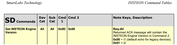
@oberkc , simply two different methods to link. Bottom line is the command shown below that is being executed by the ISY is correct (get Insteon Engine Version). If the MSII hears to command it should respond with an I2 engine version. It is not responding which leaves us with the following options: Device address is incorrect. Possible, although I've never encountered a mis-printed label. There are methods where the device can be manually linked to determine it's address. The device can't hear the PLM because of interference in the area (or PLM can't hear the MSII). Move to a different location and re-try. Faulty MSII (it happens)
-
@PapaBear , the ISY is trying to contact the MSII. It retries 3x and then times out. Did you happen to try monitoring the Event Viewer while re-connecting power to the MSII? I'm assuming you had the sensor connected previously. You also seem to be getting a lot of activity from the device @14.16.B3. I'm guessing it's a thermostat. That's both good and bad. The thermostat is communicating well with the Insteon network (do know the point of access). The bad may be the traffic it's throwing at the system. You might still try re-locating to a separate room - this will force a different RF access point to the system.
-
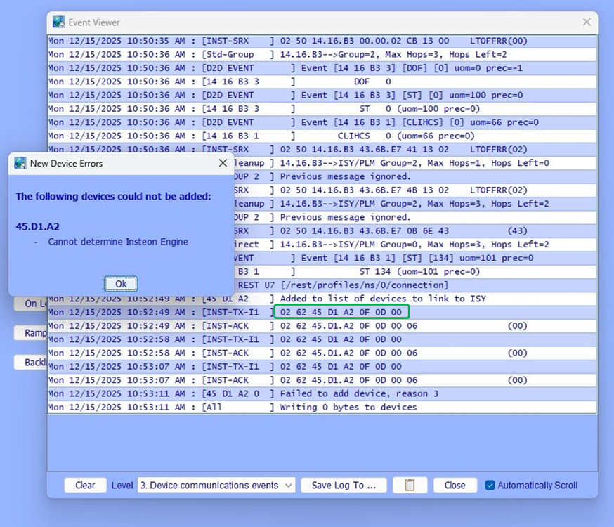
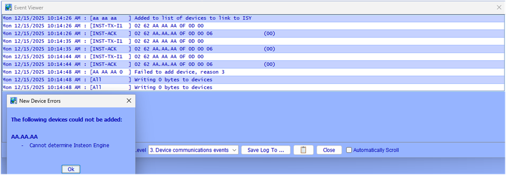
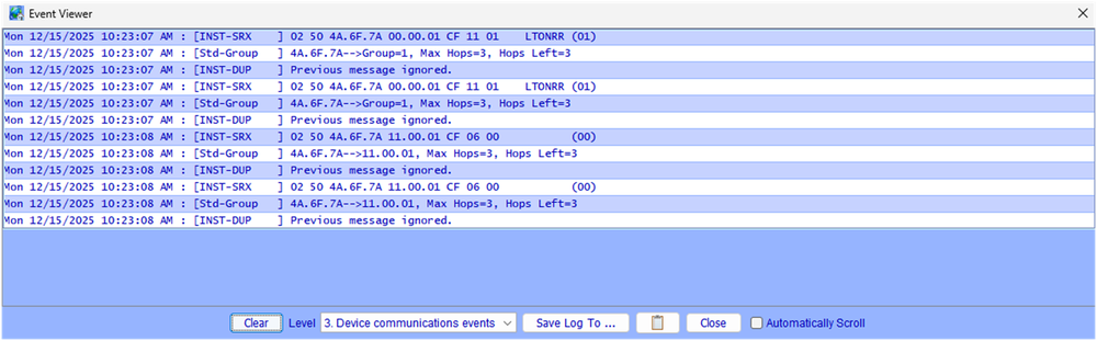
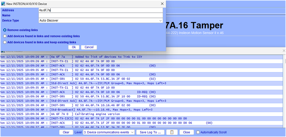
@PapaBear , I've been taking some swings at this and have not been able to reproduce what you are seeing. I've tried different communication modes (I1 vs I2), linking methods, power methods, and device versions. Things seem to just work. Would you mind posting the contents of your Event Viewer when things fail? The following is what I get when I intentionally enter in the device address. The ISY tries 3x to communicate with the device and then times out with the error message. Another possible check - If your MSII has been linked to the PLM previously, it will still contain the PLM address (even after a factory reset). Assuming the PLM still contains your MSII link (hasn't been restored from backup), you will see the MSII address pop up in the event viewer when you apply power. The communication below is from my MSII @4A.6F.7A telling the PLM that it has turned on when power is applied. Use this to quadruple check your device address (labels do get old and disfigured). The following is the method that I've settled on for linking the MSII's. Using "Auto Discover" is easier that scrolling to the bottom of the device list, and it populates the Sensor Version (v.46 below). If none of this appears to work, it is possible you simply have a defective MSII or RF Interference in the area around your PLM. You could try linking the sensor away from the PLM but close to a different RF repeater. The MSII's are 915 MHz and it's possible that you would have other devices in this range. That's not a problem that I've encountered. It is also possible that you have device(s) spamming the powerline and disrupting things while you're trying to add the device. The event monitor should show evidence if this it the case.
-
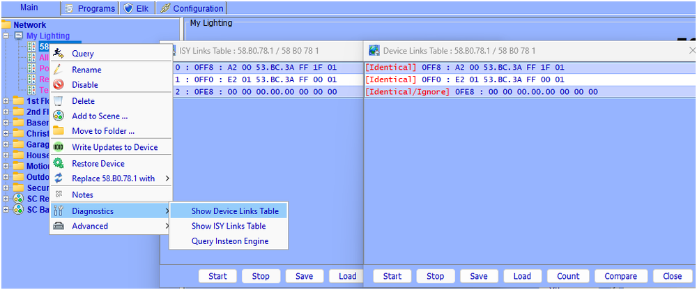
If your program turns of/off a single device, it will request a response from the device. If your program executes a scene, no cleanups are performed. Example program with a Scene ON + a device On. The event viewer output shows that the scene does not request a response from the device. Turning the device itself on will request a response. Test - [ID 0071][Parent 0003][Not Enabled] If - No Conditions - (To add one, press 'Schedule' or 'Condition') Then Set 'SC Basement Bed' On Wait 2 seconds Set 'Basement / Basement Bed' On Else - No Actions - (To add one, press 'Action') EVENT VIEWER OUTPUT ###### following is the program turning on a ascene for my basement light - no verification is performed ### Thu 12/11/2025 08:43:42 PM : [ Time] 20:43:48 7(0) Thu 12/11/2025 08:43:42 PM : [INST-TX-I1 ] 02 62 00 00 59 CF 11 00 Thu 12/11/2025 08:43:42 PM : [INST-ACK ] 02 62 00.00.59 CF 11 00 06 LTONRR (00) ###### program turning on the individual light - Light responds with 2 Hops left ######### Thu 12/11/2025 08:43:44 PM : [INST-TX-I1 ] 02 62 13 0A 51 0F 11 FF Thu 12/11/2025 08:43:44 PM : [INST-ACK ] 02 62 13.0A.51 0F 11 FF 06 LTONRR (FF) Thu 12/11/2025 08:43:44 PM : [INST-SRX ] 02 50 13.0A.51 53.BC.3A 2B 11 FF LTONRR (FF) Thu 12/11/2025 08:43:44 PM : [Std-Direct Ack] 13.0A.51-->ISY/PLM Group=0, Max Hops=3, Hops Left=2 Since your scene sounds like it is intermittent, I don't believe you have a link problem. If there were bad links, the devices would never respond. If you wish to look for bad or missing links,: Right click on a device in the admin console tree. Select "diagnostics/show device links table" Once the link table has finished populating, click the "compare" tab at the bottom of the table. A second table will open showing what the ISY believes the table should contain. Any errors will be noted in the original table. ###### Note - If you see an error flagged with a data value of ": EA" this is not an actual error. #####Devices that show errors can be corrected by right clicking the device and using the "restore device" For assessing communication issues - You can query your devices with the Event Viewer open and set to level 3. Inspect the "Hops remaining" response from the device. Normally commands are sent with max Hops = 3. Responses received back with 3 hops remaining is excellent, 0 not so much. You can also perform a scene test from the "Tools Menu". This will turn a scene on and then back off. It will request cleanups from the devices and indicate whether they responded properly. This is actually a rather rigorous test.


-
@dennisric , the "flashing" sounds like a noise and/or power supply filtering problem (capacitor dying). Are your togglelincs on the same circuit? Have you changed the loads on the switches? Any recent issues with the utility transformer/neutral line to the house? (or other electrical work). I agree that a simple reset/restore is easy and prudent. If that doesn't work you might try swapping one device out to see if that corrects the problem. The togglelincs are ~10 years old or more. Very possible that the power supply's are starting to have issues.
-
@PapaBear , when you execute a scene from your Insteon switch it will interrogate group members via a group cleanup command to verify that they received/acted on the scene command. If a device did not respond correctly, the switch MAY retry xx times. When you request a scene to be turned on using Alexa, it communicates to the ISY via a Rest command. The ISY in turn executes the scene. The difference is that when the ISY executes a scene it does NOT interrogate the scene members to see if they received/acted on the command. It assumes the command was received properly. You likely have poor communication to some of the scene members. The switch uses retries to try to improve communications. The ISY (and Alexa) do not. You can try to improve communications, or use Individual device On/Off commands (Device on/off vs scene on/off). The ISY will use group cleanups and retries for Device Direct commands.
-
@UD2)17rrh , to get directly to the point - I was wrong. I was remembering a different situation that involved non-toggle buttons (https://forum.universal-devices.com/topic/42585-kpl-button-on-level-set-to-off-not-working/). I pulled out one of my older rev 1.65 KPL's (2007 vintage) and it worked perfectly. That being the case, your KPL should function as you intended. I'd suggest trying the following in order of increasing pain: 1) Simple device restore from the admin console - you may get lucky and have a simple missing link. or 2) Delete device/ factory reset/ re-add device. Please let us know if either works.
-
@UD2)17rrh , if your KPL A button is a responder to Controller KPL B it should respond. There may be very old Insteon KPL's where this isn't the case (2008 Vintage) but anything made in the past 13 years should function. Try performing a link table read/compare. If you see errors, restore the KPL.
-
@someguy , the "E2 01 71.17.AC" link is the one that allows your device to communicate back to the PLM when it is turned on locally. Without this the PLM will not receive ON/OFF status from the device. To summarize, we've eliminated the following: Eisy to PLM serial communication errors Rest/Alexa commands to the devices Program direct commands to the devices Scene commands (your devices do not have links to support scene commands) Random All On/All Off events - your 71.C2.58 device should not respond to the All-on/All-off command In my mind that only leaves two options - Local powerline disturbance that "tricks" the device into turning on. I have seen this on some Leviton devices, but never on Insteon. It's possible, but highly unlikely that it would turn on 3 devices of different vintages (totally different power supply designs). Are these devices all on the same circuit? X10 susceptibility. Essentially the device receives a noise burst that resembles a valid X10 command. There were no X10 commands showing up in the event viewer, but X10 doesn't travel well through your powerlines or across phases. Possible the devices are seeing X10 "noise" that the PLM doesn't see. Older devices were sometimes received with X10 addresses programmed from the factory. It would be odd for your new device to have a X10 address programmed, but worth checking. A FACTORY Reset is required to remove the address.
-
Hey Someguy, thanks for posting the data. This will take a little time to go through, but let me give you some feedback. Positives: You have rather good communication with your devices, including the older ones. @kclenden and I had discussed communication errors between the PLM and Eisy. I don't see any evidence of that in your file. You had 240 I1 communications with 0 errors and 0 timeouts. While I see rest activity (seems to reoccur @5 min intervals) is doesn't seem to be directly associated with your switches. This doesn't seem to be Alexa related. Your problem devices: I see where you query the devices @4 AM (they confirm off) and again @8 AM. Problem is they respond that they are off @8 AM. I would have expected that query to show them ON. I will agree that there are no direct commands to devices 15.A6.B2 and 15.A2.CC (Can't tell if they are part of a scene). There are many 2 off and fast off commands and "Beep" commands being sent to device 71.C2.58. The 1st beep command starts @5:01 am and the Off/f-off commands start @5:15:47 AM (Line number 8071). There are a number of scenes being turned on throughout. Can't tell if your problem devices are members. Your 15.A6.B2 and 15.A2.CC devices are rather old. They will probably respond to an Insteon All-on command. Your 71.C2.58 is rather new. It should NOT respond to the Insteon All-on command. There are no X10 transmissions in the log - no evidence of X10 noise causing problems. Suggestions: Check to see what is issuing the beep/off/fast off commands to your 71.c2.58 device. This looks like a program. If your 3 problem devices are not members of any scenes, perform link table scans/compares on each. Factory reset/Restore if you see mismatches. If the device link tables check out, but they still respond during the night, It's possible that the Eisy data table is incorrect. In this case you'll need to delete/factory reset/re-add the devices.
-
@gssincla , your event viewer is showing commands being sent TO the PLM. I don't see any evidence the PLM is acknowledging the commands. The following is a section from the end of your event viewer post. There should be PLM acknowledge responses [INST- ACK] after each command sent by the ISY [INST-TX-I1]. Hopefully the PLM has simply locked up. Try a power cycling both the PLM and ISY. If that does not work, it may have given up. Sun 11/16/2025 23:25:22 : Create REST U7 [/rest/nodes/57%2030%20F4%201/cmd/DON/0/51] Sun 11/16/2025 23:25:22 : U7 Rest: submitCmd([57 30 F4 1],[DON],[<NULL>]) Sun 11/16/2025 23:25:22 : [INST-TX-I1 ] 02 62 57 30 F4 0F 13 00 MISSING PLM ACKNOWLEDGE Sun 11/16/2025 23:25:23 : Create REST U7 [/rest/nodes/57%2030%20F4%201/cmd/DON/0/51] Sun 11/16/2025 23:25:23 : U7 Rest: submitCmd([57 30 F4 1],[DON],[<NULL>]) Sun 11/16/2025 23:25:23 : [INST-TX-I1 ] 02 62 57 30 F4 0F 13 00
-
@someguy , we'll use the event viewer information to try to eliminate external "Rest" commands and PLM serial communication errors that @kclenden posted about. Since it sounds like this has been going on for some time, it appears to be different than the "Rest" event that you posted about earlier. Would you agree? Have you tried looking though the ISY log for on/off events on your problem devices? Keep in mind that you are probably looking for communication errors with the problem devices. The ISY may be telling the device to turn off, but the device doesn't hear the command.
-
@someguy , I would be interested in seen your event viewer logs. I f you could run a couple of days worth we might get some additional insight. Please also post the Insteon address of your problem devices.
-
@Geddy, thanks for confirming. I should probably know that by now, but some things just don't stick. I'm still thinking the 2477D issue sounds like an intermittent communication problem.
-
The older isy994 included a program that would query "My Lighting" at 3:00 AM to re-synchronize the system. I am guessing that the EISY has the same program. If a device does not respond during the system query your will get a "Cannot Communicate With XX.XX.XX. Please check connections" when you open the Admin Console. This sounds like what you are seeing on the 2477D. Since you can control it from the Admin Console/UD Mobile it sounds like the device is somewhat intermittent. You may have a noise source/signal absorber that is active at night and is interfering with communications. Open your Event Viewer and set to Level 3. Perform a "Query" from the admin console. It should look something like the following. The "Hops Left=3" in the communication below shows the message is being received on the 1st Hop (very good). If the Hops Left were to be 0 that would be marginal. Thu 11/13/2025 08:56:10 AM : [INST-TX-I1 ] 02 62 54 A1 F5 0F 19 00 Thu 11/13/2025 08:56:10 AM : [INST-ACK ] 02 62 54.A1.F5 0F 19 00 06 LTSREQ (LIGHT) Thu 11/13/2025 08:56:10 AM : [INST-SRX ] 02 50 54.A1.F5 53.BC.3A 2F 00 00 (00) Thu 11/13/2025 08:56:10 AM : [Std-Direct Ack] 54.A1.F5-->ISY/PLM Group=0, Max Hops=3, Hops Left=3 The fact that you cannot control the device from your program MAY be because you are using a scene. Scene control on the ISY does not verify that the device responded. It issues the command and assumes it succeeded. Commands sent from the Admin console are "Device Direct" and do verify the communications. I am not familiar with the error you are getting on the mini remote switch. It's possible that the add process didn't finish completely and the ISY is continuing to retry the addition. Could you post the model of the remote and the exact error message that you're receiving?
-
@JimTurner , Your Rest command syntax is correct for the ISY994. I don't believe there has been a syntax change in the Eisy (I do not have one). Is it possible that the program ID or IP has changed? As a follow on thought, does the Eisy allow http access (not https)?
-
My opinion, but I don't think our current discussion in any way helps with your issue. I view this as a Alexa/rest issue and I am not qualified to help in the matter. I do very much hope that you find a quick resolution. If we continue our current discussion we will be diluting possible responses/solutions.
-
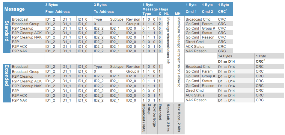
@kclenden , we have confirmation of the invalid sequence 1) 02 62 00 11 00 CF 13 00 was acknowledged by the PLM and turned all lights off (responders to group 00). 2) 02 62 00 11 00 CF 11 00 was acknowledged and turned all linked group 00 lights ON. 3) 02 62 0F 19 00 CF11 00 also acknowledge and turned all linked group 00 lights ON. I used a spare PLM that had been factory reset. I used Houselinc to link 3 devices to the PLM (group 00). All three devices were older and had been previously identified as responders to the Insteon All-on command. The PLM was an older 2413UH version V1.5 Date Code 1123. As far as the invalid format is concerned, the "Broadcast Group" command (message flag CF in the above) only considers the lower byte of the address since groups are limited to 00 to 255 (00 to FF). Group 00 is normally reserved for devices linked to the PLM. Group FF is defined as "all linked devices". I am not entirely sure how they differ. I normally use group FF for my testing. Wasn't entirely sure whether group 00 would work. I was also not sure whether the extraneous data in the upper address bytes would be rejected by the PLM. They were not. I had never considered that the PLM might miss or swap entire bytes in my testing. Your data has been an eye opener. The following is from page is from the "Insteon Whitepaper: The Details" version 2 - 2013 (page 21). I know you understand this information well. I am not trying to be insulting or pedantic. I am hoping that others may have the same Ah-Ha moment that I had when I saw your log. We are now well off the track of the OP's original thread. This may be related to what @someguy is experiencing. I do not believe it is related to @jlloyd_UD 's issue which appears to be purely Alexa base. WE should either start a new thread or ask for his blessing to continue.
-
@kclenden , thank you again for the information. I am currently writing a Python script to parse through the even viewer data. The differences between your EISY data and my ISY994 are significant. I have many instances where the ISY will issue multiple commands prior to receiving an ACK from the PLM. I am trying to implement logic to "look ahead" for proper ACK's. It's not easy (and I'm a python novice). My ISY instance hung today after roughly 50 hours. I have not seen a PLM ECHO error as yet. I will move the routine to another dedicated PC that will hopefully be able to run longer. I appreciate the offer of providing your program. Please allow me some time to poke at this from my side. I see advantages in having multiple eyes/approaches to addressing the problem. I should be able to test the invalid message sequence (02 62 00.11.00 CF 13 00) in the AM. I see no reason that this would not produce an ALL-OFF. I use the old Busyrat PLM tool to write command sequences to the PLM. I retired the old windows PC that had the tool installed. Resurrected the PC from dead storage a little while ago and verified the tool functionality. Will try executing the all off in the early AM so as not to upset family members (and the Boss).
-
@kclenden , extremely interesting log. Thank you for posting. Very nice presentation with the line numbers to correlate things. I don't want to take this thread sideways, so I'll try to be brief. Observations: 1) I have never seen mismatches like this using my ISY994. You are, however, looking far harder than I have. I have been running the event viewer since your 1st post in an attempt to find mismatches. 2) I have never experienced the "LINK INFO" message using the ISY994. This may be a EISY only message. You seem to be highlighting these occurrences. Curious if you believe it's related. 3) I do see where the PLM incorrectly acknowledged a Group Broadcast OFF command to Group 00 (line76627). If you actually witnessed an All-Off that's kind of a smoking gun. I am not sure if this is the infamous All-on/All-off from the past, or something new.
-
Wow - that is exactly what I've been theorizing was occurring at the PLM serial interface. It didn't seem logical that a powerline collision could reproduce the proper bit coding/timing/and checksums. A collision at the serial interface has far fewer checks and balances. Alas, I have never actually seen this in the event viewer (don't have a EISY). I would love to see any examples of echo back errors that you may have. I have not had any All-on events for some time, but I have been adding delays and eliminating Insteon Motion sensors tying to make the system more reliable. I would be willing to take things in the opposite direction to actively try to break the system in order to troubleshoot.
-
My kneejerk reaction is that this is (again) alexa commanding your devices on using the rest interface. The event viewer posts that you have made showed a rest command instructing the EISY to turn on the device @48.15.F2. That's a very specific device direct command. If this is still occurring, you should be able to view with the event viewer and the EISY log. I am not Alexa knowledgeable. It's possible that when you upgraded your BB Fan device you also eliminated the link in Alexa. I do use the rest interface extensively between my ISY994 and Home Assistant. I have not seen problems with miscommunication and am not sure what that would look like. My last comment relates to the age of your Insteon devices. The are older Icon powerline only devices (I still have several). I did get tripped up a while ago by a light that began responding to an X10 command (2876S V.28 Device). I still have some X10 floods that activate and announce motion. My driveway flood began turning the icon device on/off. The ISY994 was completely blind to this. A factory reset/restore eliminated the X10 address in the switch. The ISY does not (to my knowledge) give us a way to check whether devices have X10 addresses programmed. It's kind of a blind spot and the reason that I bring it up. For years protocol dictated that you factory reset every device out of the box to prevent X10 addresses that might exist from factory programming. Having said the above, it would be extremely unlikely that you happen to have 4 icon devices with X10 addresses programmed. If you suspect this is the case, let us know. They are ways of testing using x10 all-on house codes.
-
Hey Someguy, The 48.15.F2 device is absolutely being turned on by a Rest command. An external device is instructing your EISY to turn on the device. Where the command originated from I can't tell you. @kclenden posted a method above on how to interrogate the Error log file to find the IP address of the sender. Aside from that, all of the commands that I've seen posted are device direct commands. In other words the commands are targeting specific device addresses (no scenes). I am not a Alexa user. I am not sure whether that information helps.


