
IndyMike
-
Joined
-
Last visited
Posts posted by IndyMike
-
-
Edited by IndyMike
On 5/26/2026 at 3:15 PM, IndyUDIuser said: Could not read config file.
[./FILES/CONF/32FBC1.REC]
@IndyUDIuser , the ".REC" files are binary files that the ISY maintains for each Insteon device in your system. The file is a "image" of the configuration for the devices (On levels, ramp rates, scenes - and other things I don't understand).
The file is written to each time you change a device parameter, add it to a scene, or change a scene parameter. Forum posts seem to indicate that performing "scene adjustments" or "backlight changes" on a regular basis may increase the likelihood of file corruption. As with all file systems, an interrupt during file access is a sure fire way to corrupt the file. In past years, this was normally due to power interrupts, or SDcard failures.
Search 'site:forum.universal-devices.com ".rec" file' for background on the subject.
The current EISY "should" be less prone to issues due to the superior storage media. There have been a number of recent posts involving ".REC" file corruption on the EISY. My guess is that the EISY is undergoing reboot's while the ".REC" files are being written (a SWAG to be sure).
Recovery is:
Delete/RE-add device (recreates .REC file)
Restore ISY filesystem from backup
On the EISY, you can apparently replace individual device ".REC" files IF you have a valid backup. You will need to search the forum for this - I don't have an EISY - no experience.
-
@DIYguy , your event viewer shows 2 links being successfully written. If this was your initial link after "deleting/resetting/re-adding", that's appropriate.
Hopefully that gets you past the recent speed bumps.
-
25 minutes ago, DIYguy said: I think we've achieved the point of delete and attempt to add back. I did get a couple devices to respond to EISY commands but there are several remaining such as Jan's lamp (lamp on end table where she reads) that just do not respond. Shows status but no response.
See attached screen shot.
To be clear, your device is responding rather well. It's the ISY that is wriwriting incorrect information due to a corrupted file. Nothing wrong with the device itself.
In the end the result it the same - delete device/re-add.
-
It looks like that completed correctly. Unfortunately, the ISY only wrote 1 link again. It looks like the isy image for this unit may be corrupt. You can view by right clicking on the device tree and selecting /advanced/show is table. If this only shows 1-2 links you'll need to delete and re- add the device
-
-
@DIYguy , your event viewer file does not appear to be on "Level 3". It does not show the details of the communication to the device.
It also does not show any errors (appears to have completed normally).
It wrote ONLY the responder link to the PLM (1 link). You should have at least 2 links
responer to the PLM
controller to the PLM (so the device can inform the PLM of changes).
Have a look at the "ISY link table" for this device (please post). If there is only 1 link the ISY link table is corrupt.
-
@DIYguy , since you are using a hardwired signal bridge I'm guessing you have an older system. I do as well.
It would be helpfull to know what specific modules are not responding (ex: 2476d vs 2477D dual band). If the devices are single band it's possible they have been having communication issues for some time. The act of restoring them (or writing new PLM addresses) may stress your commincations enough to show the problems.
It would also be very helpful if you could post a Level 3 Event Viewer log from one of your Restore sessions.
It's possible that you may need to delete/re-add these devices but, as others have indicated, it's rather painful re-creating programs and scenes. There may well be some less invasive methods to get you back up and running with these modules.
-
On 5/21/2026 at 6:03 PM, aLf said: A few weeks have passed and this morning I noticed two more switches are full bright back light all night. I'll remedy the same way, but not sure why (or how) they are changing. Any ideas? It has to be the new eisy and firware. The backlighting was rock solid for many years on the 994. Not a problem, but just extra work.
Hey @aLf , in one of your other posts we noted that you were seeing ".REC" file errors in the event viewer. If that is still occuring it is beginning to sound like the EISY is having filesystem issues for some reason.
If you have a recent backup, restoring the EISY should correct the errors and restore your ability to write to the devices.
If you do not have a good backup - Fix your devices (delete, re-add to EISY) then make a good backup.
In either case, I would suggest opening a ticket with UD. Filesystem errors do not get better with time.
-
 2
2
-
-
From a communication standpoint, I would agree that "Status" and "Control" triggers should be equivalent. The difference is programmatic, both in the triggering and the ISY knowledge of scene membership.
Example below - 2 switches (A and B) in a scene. Switch A is manually activated and the following events occur:
PLM receives a Group 1 broadcast On from the switch @0B.B7.F8
ISY Notes the On status for the Switch
ISY notes the On Level for the Switch (this is a relay unit)
The Status change triggers programs 0023 and 0093
The ISY notes that switch 16.5C.BF is a scene member and sets its' status to on @255. Note that no communication has been received from this unit.
The status change in 16.5C.BF triggers program 0093
PLM receives a direct cleanup request from switch A
In different words, the Status trigger does rely on the ISY knowledge of scene membership. There is actually a lot that goes on under the hood here. It's also a good reason why the ISY is rather insistent on being THE controller in the system. It can't infer the status of devices that were linked outside it's knowledge.
The control trigger will operate only on the device communication itself - no inferring of scenes as related to the trigger. The ISY will still assess scene membership and status of other devices and may trigger other programs. Program A may trigger based on a control event while program B triggers due to a status event with the same device communication.
Wed 05/13/2026 08:31:17 AM : [INST-SRX ] 02 50 0B.B7.F8 00.00.01 CF 11 00 LTONRR (00) Group 1 Broadcast ON from Switch
1) Switch A Turned On
Wed 05/13/2026 08:31:17 AM : [Std-Group ] 0B.B7.F8-->Group=1, Max Hops=3, Hops Left=3
Wed 05/13/2026 08:31:18 AM : [D2D EVENT ] Event [B B7 F8 1] [DON] [0] uom=0 prec=-1
2) ISY Notes On status
Wed 05/13/2026 08:31:18 AM : [ B B7 F8 1] DON 0
Wed 05/13/2026 08:31:18 AM : [D2D EVENT ] Event [B B7 F8 1] [ST] [255] uom=100 prec=0
3) ISY Notes On Level
Wed 05/13/2026 08:31:18 AM : [ B B7 F8 1] ST 255 (uom=100 prec=0)
Wed 05/13/2026 08:31:18 AM : [D2D-CMP 0023] STS [B B7 F8 1] ST Converted values Event=100 Condition=0 prec=0
4) Program status Triggers
Wed 05/13/2026 08:31:18 AM : [D2D-CMP 0023] STS [B B7 F8 1] ST op=6 Event(val=255 uom=100 prec=0) != Condition(val=0 uom=51 prec=0) --> true
Wed 05/13/2026 08:31:18 AM : [D2D-CMP 0093] STS [B B7 F8 1] ST Converted values Event=100 Condition=0 prec=0
Wed 05/13/2026 08:31:18 AM : [D2D-CMP 0093] STS [B B7 F8 1] ST op=6 Event(val=255 uom=100 prec=0) != Condition(val=0 uom=51 prec=0) --> true
Wed 05/13/2026 08:31:18 AM : [D2D EVENT ] Event [16 5C BF 1] [ST] [255] uom=100 prec=0
5) ISY Notes Scene B Switch On
Wed 05/13/2026 08:31:18 AM : [ 16 5C BF 1] ST 255 (uom=100 prec=0) Scene Member Switch noted as On
Wed 05/13/2026 08:31:18 AM : [D2D-CMP 0093] STS [16 5C BF 1] ST Converted values Event=100 Condition=0 prec=0
6) Program Status Triggers
Wed 05/13/2026 08:31:18 AM : [D2D-CMP 0093] STS [16 5C BF 1] ST op=6 Event(val=255 uom=100 prec=0) != Condition(val=0 uom=51 prec=0) --> true
Wed 05/13/2026 08:31:18 AM : [INST-SRX ] 02 50 0B.B7.F8 53.BC.3A 45 11 01 LTONRR (01)
7) Switch A Cleanup to PLM
Wed 05/13/2026 08:31:18 AM : [Std-Cleanup ] 0B.B7.F8-->ISY/PLM Group=1, Max Hops=1, Hops Left=1
Wed 05/13/2026 08:31:18 AM : [INST-DUP ] Previous message ignored.
-
21 hours ago, dbwarner5 said: I may have missed something in your description, but it seem like you are over thinking this?
Wouldn't just one program that test the status of all the lights in the basement with ORs such that if on, turn on the keypad, if all off then turn keypad off?
This would be your IF:
Basement / RecRm / Devices / Rec_ByPat_Far I3' Status is not Off
     Or 'Basement / RecRm / Devices / Rec_ByPat_Mid I3' Status is not Off
     Or 'Basement / RecRm / Devices / Rec_ByPat_Near I3' Status is not Off
     Or 'Basement / RecRm / Devices / Rec_ByStrPad1_Near' Status is not Off
     Or 'Basement / RecRm / Devices / Rec_ByStr_Mid' Status is not Off
     Or 'Basement / RecRm / Devices / Rec_ByStr_Far' Status is not Offf
THEN:
Turn on keypad
ELSE
turn off keypad.
I have to agree that this is a very elegant solution. I had previously used 2 programs to test for "All OFF" in a scene (device1 and device2 and... OFF) along with a "Any On" program (device1 or device2 or .... > 0 ).
I learned something today - that's a good day.
My one comment would be that polling devices is not without merit depending on the communication level and criticality of the system. I would not, however, implement the polling based on a state change. The thinking here is that, if you have marginal communications, you may miss the state change from the device. Better to have a free running program that polls the devices in the scene.
Case in point, my X10 floodlamps. I have a X10 booster near the PLM. Communications from the PLM to the X10 floodlamps are VERY reliable. Communications from the Flood lamps back to the PLM are less than stellar. Because of this I poll the Floodlamps at regular intervals to determine their status. The same issue can result in Insteon systems (less prevalent) depending on local PLM/Device line loading.
I use the following for polling the floodlights during the day. It runs freely during the timeframe note at 15 minute intervals. Make sure "run at startup" is enabled. For Insteon, substitute a "Query scene XX" for the "Send X10 Status Request"
Flood Daytime Poll - [ID 0041][Parent 0002][Not Enabled][Run At Startup] If From Sunrise + 1 minute To Sunset - 10 minutes (same day) And Time is Last Run Time for 'Flood Daytime Poll' + 15 minutes Then Send X10 'F1/Status Request (10)' Wait 9 seconds Send X10 'F3/Status Request (10)' Wait 9 seconds Send X10 'F5/Status Request (10)' -
9 minutes ago, SMonk said: Interesting on the using the switches to dim the lights - are we not supposed to do that? I do it all the time in one of our rooms - curious about what the alternative might be?
It's simply difficult to detect with a program. You have to add specific tests (triggers) for Fade Up/Fade Down. I don't happen to use the feature, but many of my family members do. I've been out-voted (even though I've declared our household a Monarchy).
-
 1
1
-
-
5 hours ago, SMonk said: Hi,
Quick question related to programs. I am trying to initiate a program when a switch (in this case an I3 paddle) has changed (I don't care what has changed - anything will do).
When I look at the "If" options for a control (namely the I3 paddle) - there is a multitude of possibilities (on/off/fast on/fast off/fade up/fade down ....yada yada yada). Is there anything in the "if" option testing a control just to ask "if this control did anything"? - so therefore reducing (or eliminating) a multitude of "or" statements?
This becomes particularly apparent/inefficient when I am trying to perform this set of tests across three switches - so I have 9 "or" statements for each switch - so 27 or statements in the program - I come from a programming background (not this kind) and having this many "or" statements was a little silly (usually there were single line alternatives).
@SMonk , this all depends on how fine you want to slice this onion...
If you want to detect state changes then @dbwarner5 advice will perform well. For the ON state this will catch:
Standard on (to preset level)
Additional button press (to 100% level
Fast ON
It will not catch fade up (or analogous fade down). While these are rare, I do have guests that regularly tap and hold switches to brighten lights.
After many years I have given up on educating family/friends on proper dimmer usage and have incorporated fade up/down in my programming.
To be fair, they have acquiesced on a multitude of my failings... Fair is fair
-
1
-
3 hours ago, SMonk said: Hello All (long post - sorry),
In a bit of a quandary related to the best way to approach a process - so looking for advice. I will describe below the situation - and then what I "think" is the best way to do this (then ask for guidance related to the specifics).
Situation:
I have a Rec Room in my basement that has three banks of lights. Each bank of lights is controlled independently from both sides of the large room (so each bank is set up as a two way). In this case I have an I3 Paddle connected to each "load" and then on the far side of the room there is a 2477S for each circuit. Each I3 Paddle and 2477S is set up in a scene to act as the two way - with both objects as controllers. Works perfectly fine.
At the top of the basement stairs I have installed a 6 button keypad linc - and one of the buttons on this keypadlinc I want to use to either turn on or off all three banks of lights (so one keypad linc button to rule them all).
I can (and have) created a scene where the keypad linc button is the controller - and each of the other objects are responders (lets call this the "Ruling Scene") - so when I use the button at the top of the stairs this has an immediate response from everything else (either quickly on or quickly off).
This issue is when someone turns one of the banks of lights on or off directly from the I3 Paddles or 2477S switches - I need the keypad linc button to stay "in-sync" with the status of the lights in the basement. Basically if anything is on - or partially on as the lights are dimmable - then the keypad linc button should be either turned on/lit or should stay on (if it was already lit), and vice versa - if someone in the basement turns off the last light from either a 2477S or a I3 paddle then the keypad linc button light should get extinguished.
I thought that the best way would be as follows:
Create a scene with the keypad linc button as a responder (to use in a program) - lets call this the "Master LED" Scene (using a scene as not sure about the effectiveness of directly addressing a keypad linc button in a program).
Create a program that is initiated when ANY action is performed on ANY of the switches in the basement (any of the I3 paddles or 2477S switches) - this ties in to a previous post I made about trying to find any easy way to determine if any action has been performed on a switch) - in this program if anything has "happened" then check the state of any of the basement switches (are any on, or partially on - and if so then set the "Master LED" scene to on - otherwise set the "Master LED" scene to off).
Just in case the above sometimes flakes out and maybe a signal gets dropped create another program that schedules itself at regular intervals (say 5 minutes?) that polls the state of the I3 Paddles or 2477S switches - and again - if any are on/off then set the "Master LED" scene on or off respectively - then wait 5 minutes and initiate the polling program (i.e. call itself) once again
Does anyone have a different or better approach to do this?
One thing I am not sure about - if the program sends an "on" to the "Master LED" scene due to ONE of the banks of lights being turned on in the basement - will this then trigger the "Ruling Scene" thereby turning on all the lights in the basement (which I do not want to occur - I want to just light the LED on the keypad linc so it can then be used to turn anything off that is "on' in the basement if someone leaves the basement via the stairs and uses the button at the top of the stairs)?
Any help/guidance (and best practices for the programs) would be most welcome.
@SMonk ,
I've used "master" KPL buttons for years to indicate/control the status of different scenes in my home. I typically use things like 1st Floor, 2nd Floor, Basement, and outside. The setup is very similar to what you described. I typically use the KPL buttons in non-toggle-off mode since I only use them to turn things off, but the concept is the same. Your query program is adding a failsafe that I never implemented.
My one comment would be that this does become a maintenance item when you add/delete things from your Rec Room scenes. You will need to update your programs the monitor the device(s) status accordingly. This has tripped me up frequently over the years.
If you happen to be a Home Assistant user, there is an easier solution to the programming.
-
1
-
Hey @aLf ,
The on thing that jumps out is the following error from your event viewer -
Sun 05/10/2026 09:26:30 AM : DB: Cannot load ./FILES/CONF/3BDFFC.REC
I've seen this error reported on the forum, but have not experienced it myself. Seems to be a missing "REC" file for your device at address 3BDFFC.
Ive seen forum posts where this error was associated with writing "Scene level commands" to devices. I haven't seen it associated with writing LED backlight levels, but that is a very similar operation.
Solutions that I've seen on the forum involve deleting the device and re-adding to recreate the file structure.
If you have a recent EISY backup that should restore the file system.
Past that, you may want to consider opening a ticket.
-
1
-
-
1 hour ago, SMonk said: Hi @IndyMike - I have restored devices in the admin console - is that what you mean by asking "have you performed any EISY restores lately?". If not and there is another type of restore - can you explain?
Thanks!
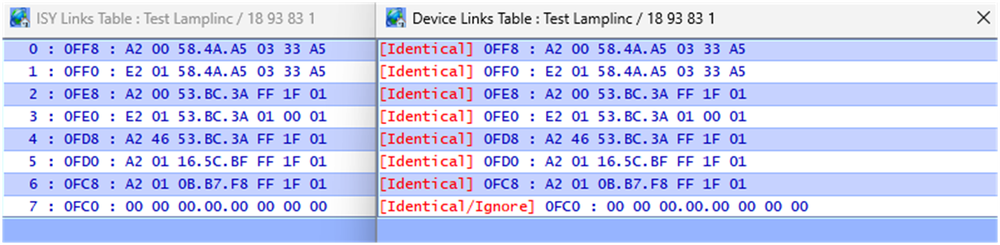
@Smonk, I was referring to the Restore operation for the EISY itself (restore from backup). This is similar to restoring any computer system from backup. The difference in this instance is that your Insteon system is "distributed" with software in the ISY, PLM, and your devices. The ISY does a good job of coordinating things, buy they can get out of synch.
Here's the scenario -
I backup the ISY to file
At this point the backup file contains a copy of all device tables
I modify a device by adding (or deleting) it from a scene
I restore the ISY from the backup in step 1 (backup now invalid).
The ISY now believes the device in step 3 has a "different" link table. Any future operation (restore, add to scene, remove from scene) will cause the scene links to be overwritten.
The confusing factor here is that the device will operate normally (it has the correct link table) until you restore/add to a scene/ remove from a scene after which the link table will be overwritten with outdated information.
Step 1: Backup ISY
Step 2: contents of "test device" vs ISY table (things match")
Step 3: Add Device to scene - ISY and Device table match (links added)
Step 4: Restore ISY from earlier backup (backup now outdated)
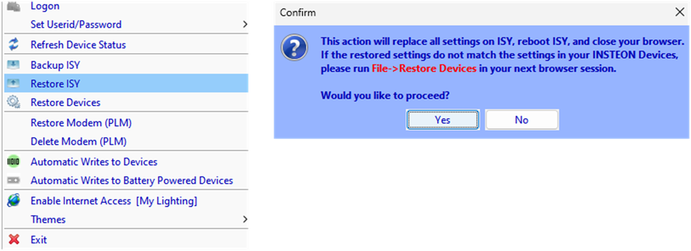
Step 5: After restore, ISY device table no longer matches actual device. The device will operate properly, but future operations (add to scene, restore, etc) will overwrite links after the ISY end of record address (x0FD8)
-
@aLf , the phenomena that @hart2hart is referring to is actually "wear out" of the memory location. If this is the case, a reset would not work.
It's always possible that the devices have been "upset" by a power anomaly. A quick power cycle could help.
It's also possible that the devices are not correctly linked after your transition to the EISY. If you could provide a Level 3 Event Viewer capture of the communication when you manually change the backlight we may be able to help diagnose.
The following is a capture from changing one of my 2477S to max backlight [7F] and back to min [00]. Memory location is 0x0264.
Sun 05/10/2026 06:24:44 AM : [All ] Writing 1 bytes to devices Sun 05/10/2026 06:24:44 AM : [INST-TX-I2CS] 02 62 1F BE 7A 1F 2F 00 00 00 00 00 01 00 00 00 00 00 00 00 00 D0 Sun 05/10/2026 06:24:44 AM : [INST-ACK ] 02 62 1F.BE.7A 1F 2F 00 00 00 00 00 01 00 00 00 00 00 00 00 00 D0 06 (00) Sun 05/10/2026 06:24:45 AM : [INST-SRX ] 02 50 1F.BE.7A 53.BC.3A 2F 2F 00 (00) Sun 05/10/2026 06:24:45 AM : [Std-Direct Ack] 1F.BE.7A-->ISY/PLM Group=0, Max Hops=3, Hops Left=3 Sun 05/10/2026 06:24:45 AM : [INST-ERX ] 02 51 1F BE 7A 53 BC 3A 15 2F 00 00 01 0F FF 00 A2 00 53 BC 3A FF 1F 01 B8 Sun 05/10/2026 06:24:45 AM : [Ext-Direct ] 1F.BE.7A-->ISY/PLM Group=0, Max Hops=1, Hops Left=1 Sun 05/10/2026 06:24:45 AM : [1F BE 7A 1 ] Memory : Write dbAddr=0x0264 [7F] cmd1=0x2E cmd2=0x00 Sun 05/10/2026 06:24:45 AM : [INST-TX-I2CS] 02 62 1F BE 7A 1F 2E 00 00 07 7F 00 00 00 00 00 00 00 00 00 00 4C Sun 05/10/2026 06:24:45 AM : [INST-ACK ] 02 62 1F.BE.7A 1F 2E 00 00 07 7F 00 00 00 00 00 00 00 00 00 00 4C 06 (00) Sun 05/10/2026 06:24:46 AM : [INST-SRX ] 02 50 1F.BE.7A 53.BC.3A 2F 2E 00 (00) Sun 05/10/2026 06:24:46 AM : [Std-Direct Ack] 1F.BE.7A-->ISY/PLM Group=0, Max Hops=3, Hops Left=3 Sun 05/10/2026 06:24:46 AM : [All ] Writing 0 bytes to devices Sun 05/10/2026 06:25:31 AM : [All ] Writing 1 bytes to devices Sun 05/10/2026 06:25:31 AM : [INST-TX-I2CS] 02 62 1F BE 7A 1F 2F 00 00 00 00 00 01 00 00 00 00 00 00 00 00 D0 Sun 05/10/2026 06:25:31 AM : [INST-ACK ] 02 62 1F.BE.7A 1F 2F 00 00 00 00 00 01 00 00 00 00 00 00 00 00 D0 06 (00) Sun 05/10/2026 06:25:31 AM : [INST-SRX ] 02 50 1F.BE.7A 53.BC.3A 2F 2F 00 (00) Sun 05/10/2026 06:25:31 AM : [Std-Direct Ack] 1F.BE.7A-->ISY/PLM Group=0, Max Hops=3, Hops Left=3 Sun 05/10/2026 06:25:31 AM : [INST-ERX ] 02 51 1F BE 7A 53 BC 3A 11 2F 00 00 01 0F FF 00 A2 00 53 BC 3A FF 1F 01 B8 Sun 05/10/2026 06:25:31 AM : [Ext-Direct ] 1F.BE.7A-->ISY/PLM Group=0, Max Hops=1, Hops Left=0 Sun 05/10/2026 06:25:32 AM : [1F BE 7A 1 ] Memory : Write dbAddr=0x0264 [00] cmd1=0x2E cmd2=0x00 Sun 05/10/2026 06:25:32 AM : [INST-TX-I2CS] 02 62 1F BE 7A 1F 2E 00 00 07 00 00 00 00 00 00 00 00 00 00 00 CB Sun 05/10/2026 06:25:32 AM : [INST-ACK ] 02 62 1F.BE.7A 1F 2E 00 00 07 00 00 00 00 00 00 00 00 00 00 00 CB 06 (00) Sun 05/10/2026 06:25:32 AM : [INST-SRX ] 02 50 1F.BE.7A 53.BC.3A 2F 2E 00 (00) Sun 05/10/2026 06:25:32 AM : [Std-Direct Ack] 1F.BE.7A-->ISY/PLM Group=0, Max Hops=3, Hops Left=3 Sun 05/10/2026 06:25:32 AM : [All ] Writing 0 bytes to devices -
@SMonk, Pauls' scenario is certainly plausible. God knows I've thumb fingered setting often enough and turned scenes off (0%) when I intended on. Unfortunately, from your description, the error would need to occur on multiple 2477S's.
Since a restore did not work, the eisy believed the switch programming was correct.
The only thing I can come up with is a eisy restore from a backup that dated prior to the switches being added to the original scene. The EISY device table would not have had the links to that scene. Adding the devices to a new scene would have over written the scene that the EISY didn't have knowledge of.
Have you performed any EISY restores lately?
-
Edited by IndyMike
On 4/24/2026 at 5:40 PM, IndyUDIuser said: Why did the simple act of adding devices to a scene corrupt so many links, both in the devices themselves and in the EISY? Rather frustrating.
As others have indicated, the ISY wants to be THE controller in the system. It maintains an image of each device memory table.
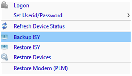
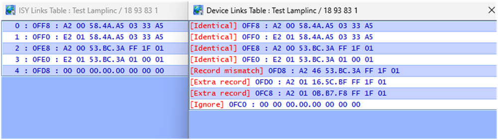
You can view a device link table by right clicking the device in the Admin tree and selecting:
Diagnostics/Show device links table: reads from the physical device
Diagnostics/Show ISY Links Table: displays what the ISY believes the device link table should contain (the image)

The following is a table comparison (read vs image) for a test lamplinc I have. It contains only two links and an "End OF Record" entry @0FE8.

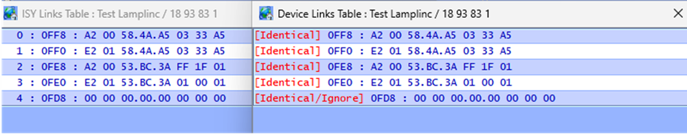
If I link the device to my houselinc installation (without informing the ISY), the ISY994 now shows mismatched records when performing a table read/compare.

Further performing an ISY scene add on this device Does overwrite the link records to the Houselinc install (links to 58.4A.A5 overwritten). This is because the ISY image shows the previous END OF Record being @0FE8

The ISY994 will allow you to import links contained in a Device, HOWEVER this must be done when you 1st add the device to the ISY. After that, the ISY wants to be in control. Manual links (outside the ISY knowledge) will be overwritten when adding scenes or restoring devices.

Lamplinc added with existing links to Houslinc PLM @58.4A.A5. ISY PLM @53.BD.3A correctly added afterward.

-
3
-
@kvolger , glad that you've thought through a few of the failure scenarios. It sounds like you are comfortable with the system risks.
I hope things work well for you.
-
2
-
-
20 hours ago, kvolger said: Thank you again for you time and effort on this issue.
I have not received the Insteon 2450 IO yet, being down in the Baja California Sur is a bit more complicated than residing in Los Angeles, CA.
Guy Levoie: That works because the status of the level sensor will remain at ON during the time that the program is waiting 10 minutes before continuing and turning on the pump. Adding a wait like that is a good practise, it adds hysterisis to the control system, preventing short run cycles of the pump.
That is the exact reason I wanted to add the Wait command with appr. 10minutes to the program.
oberkc: I am failing to see why the single program would not work. Use "STATUS" condition for the water level sensor (IOLinc sensor wired to something, I assume).
I shall test the single program after having the 2450 IO in my hands, otherwise the two program would be an easy solution to use.
The reason for all this: The fill pump for this water storage tank, used to be a very expensive and sophisticated deep well solar pump. During solar hours it was filling the tank, and then provided watersystem pressure for house and irrigation. This solar pump was solely controlled by an inline pressure switch. After daylight hours the standard pressure pump took over, only drawing water from the storage tank and providing watersystem pressure. Being controlle by a separate pressure switch.
The expensive solar pump went kaputt, and the replacement well pump would be able to fill the tank, but could not create the necessary needed watersytem pressure, the control via a pressure switch would not work any longer.
A simple float switch is not an option for this project.
Water is being drawn from this tank at various times of the day, and the new fill pump is supposed to keep the tank full, right now temp. programmed at four fixed times with a 15minutes run time each.
Your description of the pumping system concerns me. It sounds like you are transitioning from a dedicated system with hardwired sensors/safeties to a distributed system with communicating sensors/safeties. This doesn't sound like something that I would trust to home automation devices. At least not without backup sensors and over-rides (yes I've been burned).
The 2450 IOLinc may seem like a handy solution, but it is powerline only communication (prone to communication errors) and will respond to Insteon All-on errors. I am not sure that the All-on matters if you are using it in a "sensor only" configuration.
The micro ON/OFF switches are more recent technology and MAY be immune to All-On/OFF commands. Please do test this.
Beyond the above, you need to think through failure modes:
What happens if an micro on/off doesn't receive communication and doesn't turn on/off?
Same for the 2450 - it doesn't transmit the contact open/close.
What happens if the system is running and power fails?
What happens when power is restored (many modules will default to the last power state).
Sorry to be Debbie Downer here, but I'm concerned the "criticality" of this system. What happens when something doesn't turn on/off as planned? Is it a minor inconvenience, a moderate cost, or a major explosion?
If the answer is an inconvenience, then by all means proceed. If other, then not as much.
-
2
-
I'm glad I'm not the only one. It's really bad when things suddenly break for some unknown/unfathomable reason.
It's worse when I realize that I AM THE Reason.
Like @dbwarner5, I use the find/replace feature often. I also disable programs and folders to prevent things from running unintentionally. Stuff still happens. More and more I am finding that my Home Assistant "test" programs are being re-enabled (me again) and running when they shouldn't.
I have to say that UD did things right with their program/folders/variable organization setup. I wish HA would adopt something similar.
-
On 4/10/2026 at 10:38 AM, IndyUDIuser said: I have this program that I am trying to use to set an integer variable to the current day of the month. When I run the THEN clause the INIT value is correct but the variable iCurrentDayOfMonth is set to zero. This doesn't make sense. I expect them both to be the same. I have a couple of other similar programs using different variables and they work fine. What is going on? TIA
DATTM SetCurDayOfMonth - [ID 0047][Parent 0028]
If
- No Conditions - (To add one, press 'Schedule' or 'Condition')
Then
$iCurrentDayOfMonth = [Current Day of Month]
$iCurrentDayOfMonth Init To $iCurrentDayOfMonth
Else
- No Actions - (To add one, press 'Action')
I just tried this on my ISY994 and it works as expected (I have not used the "Init to" previously).
Since you have other programs working properly, I'm going to guess that your program didn't save properly for some reason. When this has happened in the past I've found it easiest to simply delete the program and start over. Do NOT copy the program. The visual representation will look correct, but the XML may be incorrect.
-
2
-
-
-


Should I upgrade from ISY994i to eisy?
in eisy
Seems like @matapan had similar issues with the "FS" format command.